Molding system and method of heating a material inside a molding system

a molding system and molding technology, applied in the field of molding machines, can solve the problems of large and costly power sources for traditional injection molding systems, the loss of shear heat, and the inability to take only 10-25% of the molding tim

Inactive Publication Date: 2016-09-29
EXTRUDE TO FILL
View PDF0 Cites 24 Cited by
  • Summary
  • Abstract
  • Description
  • Claims
  • Application Information

AI Technical Summary

Benefits of technology

[0012]The present disclosure generally provides a molding system, which may be referred to herein as an extrude-to-fill (ETF) molding system, and a method of heating a material inside a molding system. In some embodiments, a molding system may include a magnetic screw received inside a thermally-insulative barrel, and the screw may be indu

Problems solved by technology

The recovery extrusion stage may take only 10-25% of the entire molding time such that the shear heat may also be lost when the extrusion screw does not rotate except during the recovery extrusion stage.
The traditional injection molding system requires large and costly power sources for both the injection system 118 and the clamp system 120.
These power sources must be supported by a massive machine structure, which increases facility infrastructure costs including electrical supply, thick concrete footings or floors and oversized HVAC systems that

Method used


Image

  • Molding system and method of heating a material inside a molding system
  • Molding system and method of heating a material inside a molding system
  • Molding system and method of heating a material inside a molding system

Examples


Embodiment Construction

[0038]The present disclosure may be understood by reference to the following detailed description, taken in conjunction with the drawings as described below. It is noted that, for purposes of illustrative clarity, certain elements in various drawings may not be drawn to scale.

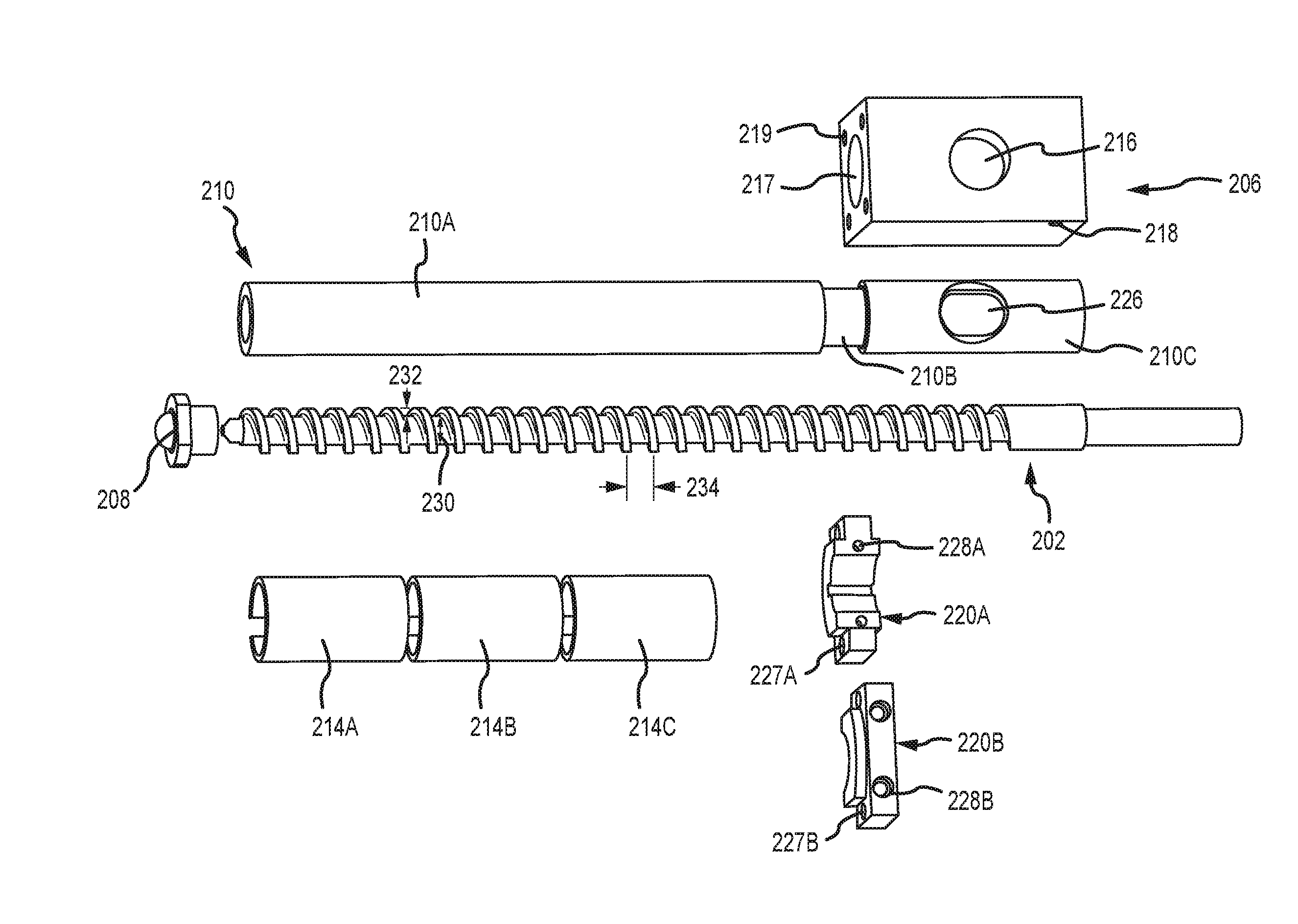
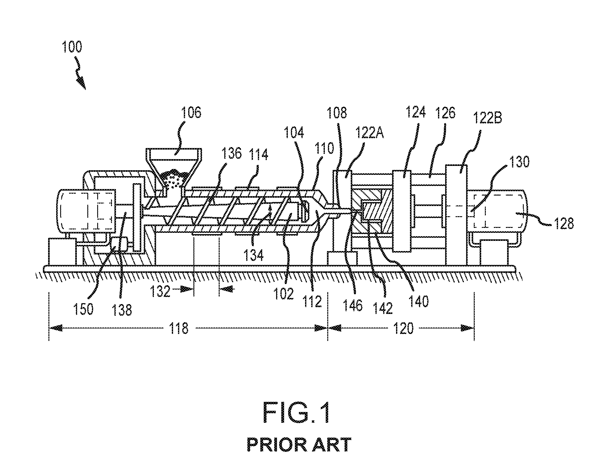
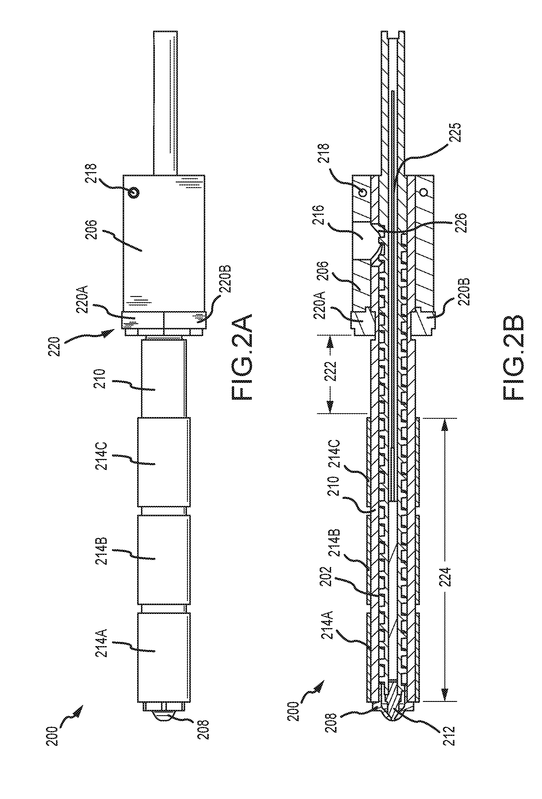
[0039]The present disclosure generally provides a molding machine, which may include a molding system and a clamp system. The molding system may include an extrusion screw that extrudes on demand to transfer or pump molten material into a mold with an unlimited or varying shot size or volume of displacement, without requiring a purging process after periods of idle time. In traditional injection molding systems, the shot size is fixed and is the material volume that can be displaced or transferred into the mold during an injection cycle, sufficient to fill a single mold cavity or a plurality of mold cavities. The varying shot size of the ETF molding system is different from the fixed shot-size of traditional in...


PUM

PropertyMeasurementUnit
Temperatureaaaaaaaaaa
Lengthaaaaaaaaaa
Sizeaaaaaaaaaa

Abstract

The present disclosure provides a molding system and a method of heating a material inside a molding system. The molding system may include a thermally-insulative barrel, a screw received inside the barrel and rotatable relative to the barrel, and a heat source received inside the barrel for heating an annular space defined between the barrel and the screw. The method of heating a material inside a molding system may include applying inductive heat to a magnetic screw positioned inside an insulative barrel to prepare a material for extrusion.

Description

CROSS-REFERENCES TO RELATED PATENT APPLICATIONS[0001]This patent application is a continuation-in-part of U.S. patent application Ser. No. 14 / 959,921, entitled “Injection Molding System and Method of Fabricating a Component”, filed on Dec. 4, 2015, is a continuation-in-part of International Patent Application Number PCT / US2015 / 064045, entitled “Injection Molding System and Method of Fabricating a Component”, filed on Dec. 4, 2015, is a continuation-in-part of U.S. patent application Ser. No. 14 / 960,115, entitled “Nozzle Shut Off for Injection Molding System”, filed on Dec. 4, 2015, is a continuation-in-part of International Patent Application Number PCT / US2015 / 064110, entitled “Nozzle Shut Off for Injection Molding System”, filed on Dec. 4, 2015, is a continuation-in-part of U.S. patent application Ser. No. 14 / 960,101, entitled “Control System for Injection Molding”, filed on Dec. 4, 2015, and is a continuation-in-part of International Patent Application Number PCT / US2015 / 064073, en...

Claims


Application Information

Patent Timeline
IPC IPC(8): B29C47/84B29C45/74B29C35/08
CPCB29C47/842B29C2035/0816B29C45/74B29C35/0805G05B2219/2624B29C45/60B29C45/62B29K2995/0008B29K2995/0015
Inventor FITZPATRICK, RICHARD ERNEST
Owner EXTRUDE TO FILL
Why Eureka
Try Eureka