Motor, controller and associated method

Active Publication Date: 2016-09-29
REGAL BELOIT AMERICA
View PDF9 Cites 12 Cited by
  • Summary
  • Abstract
  • Description
  • Claims
  • Application Information

AI Technical Summary

Benefits of technology

The patent describes a pump motor that has a sensor to measure its performance. The motor also has a timer or clock that helps to optimize its usage by coordinating with a controller. The technical effect is that the motor uses less electricity, resulting in lower costs.

Problems solved by technology

Scheduling such consumption can be difficult or inconvenient, particularly where the methodologies are complex.

Method used


Image

  • Motor, controller and associated method
  • Motor, controller and associated method
  • Motor, controller and associated method

Examples


Embodiment Construction

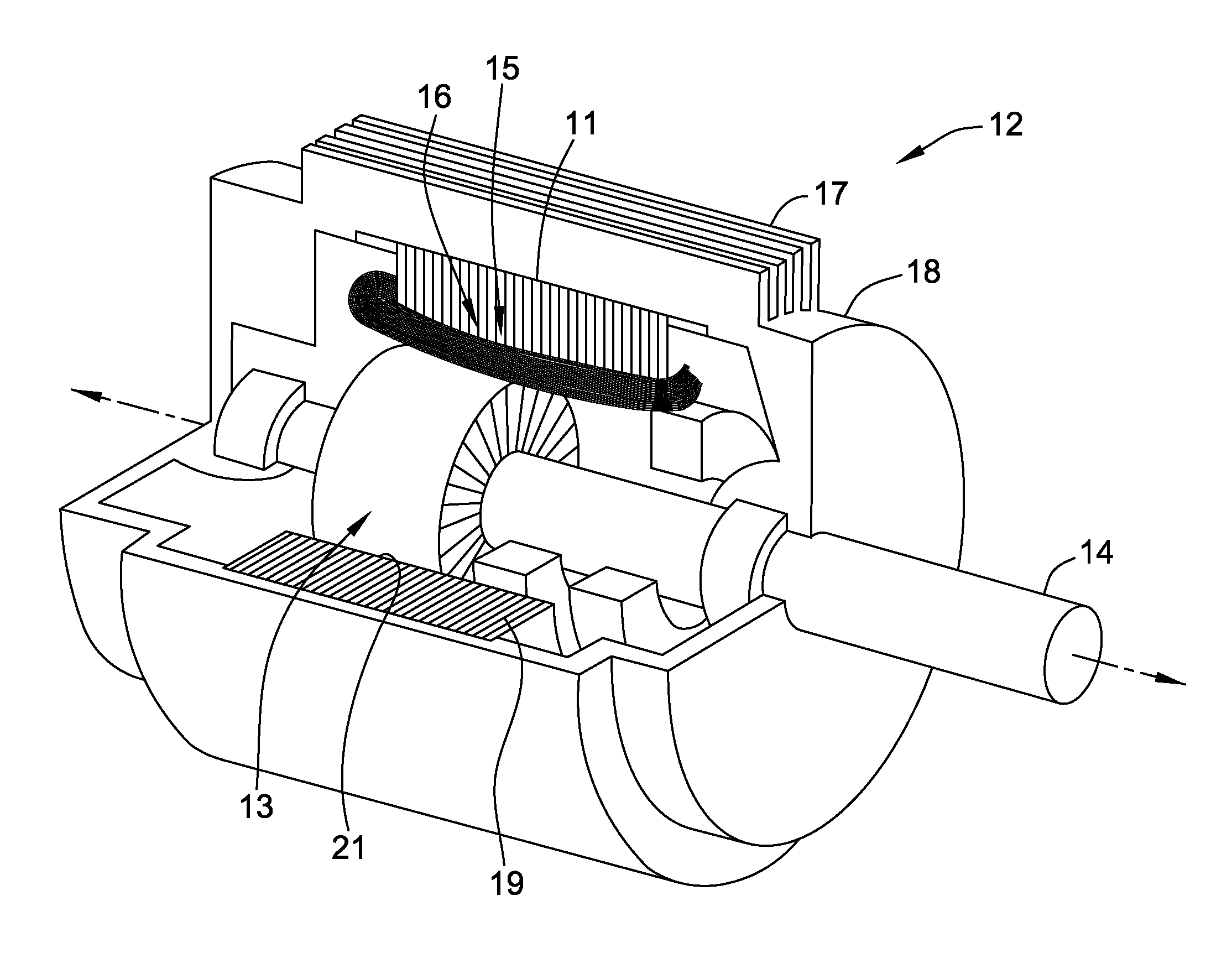
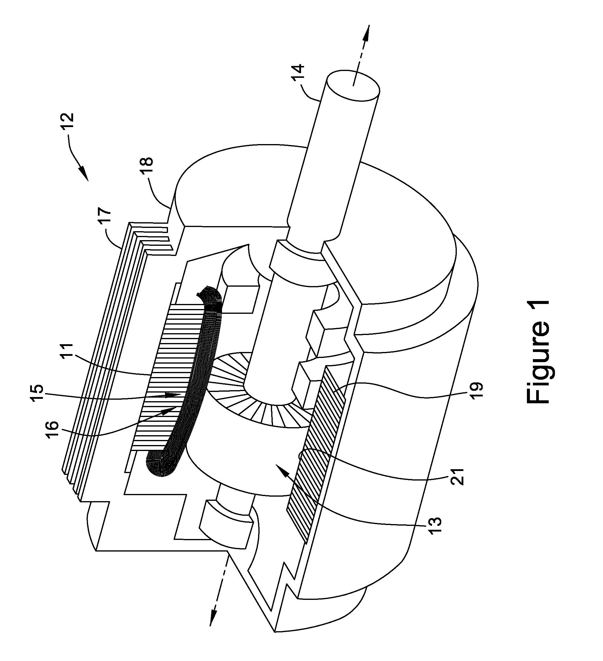
[0035]Pools and spas are typically equipped with pumps to circulate water within the pools and spas to maintain a pleasant condition for the water in the pool. Pumps and pump motors are designed to be able to circulate the water within the pool or spa sufficiently while operating for only a portion of the time.

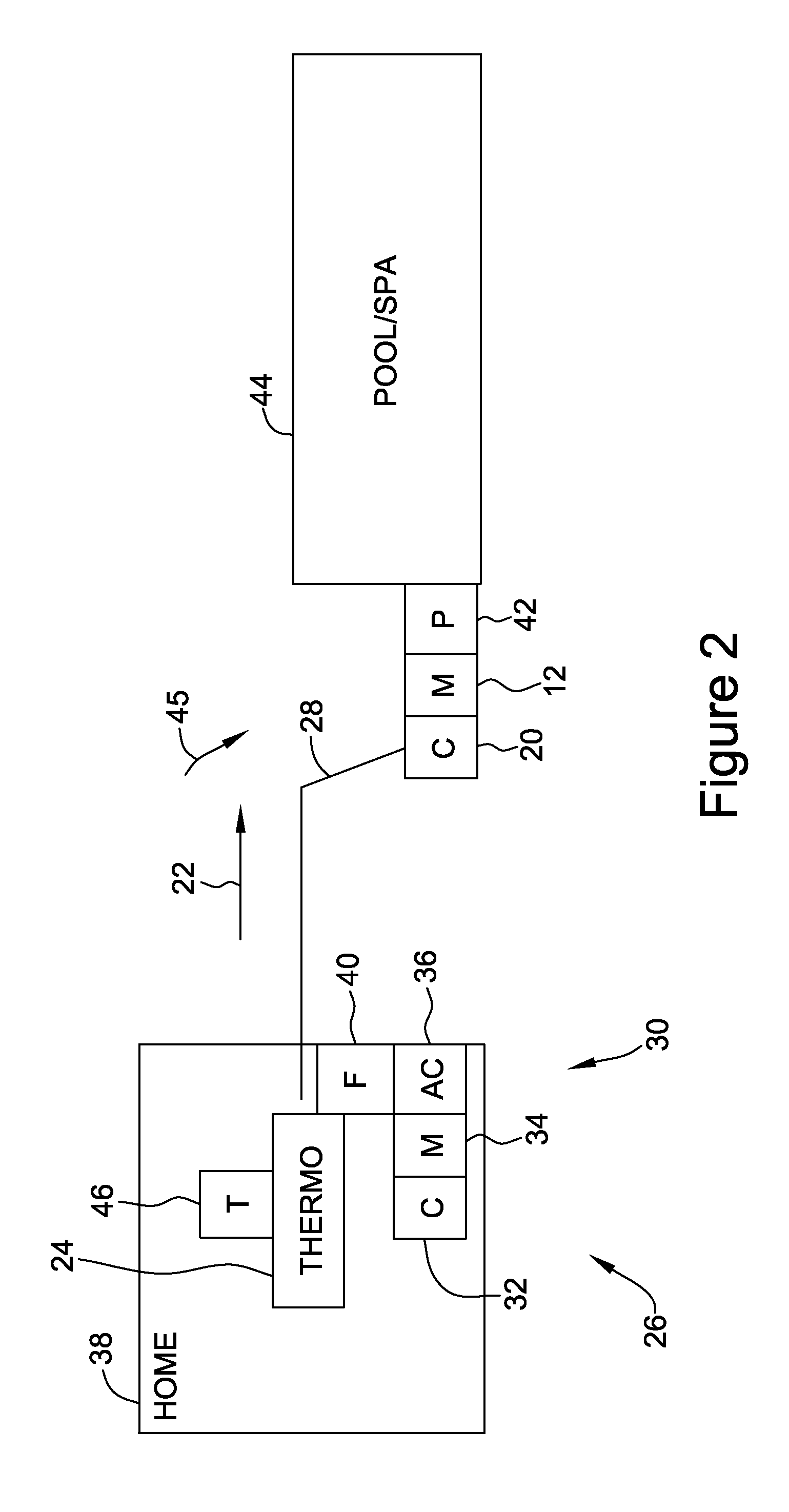
[0036]Energy consumption from energy providers tends to vary during different days of the week and at different times of the day. Energy provided by the energy providers must be capable of meeting the demands of the consumer at all times, particularly at times of highest energy consumption. Due to the enormous capital expenses required to construct and maintain the infrastructure necessary to provide electrical power to residential consumers, energy providers have devised methodologies to discourage energy use at those times of highest energy consumption.

[0037]These methodologies are based in part on demand response (hereinafter “DR”). DR is defined as changes in electric usag...


PUM


Abstract

According to an embodiment of the invention, a pump motor controller for managing energy usage of a pump motor and for receiving signals from a signal sending device corresponding to the status of a climate control device is provided. The motor controller is adapted to receive the signal and to control the pump motor at least partially based on the signal.

Description

BACKGROUND OF THE INVENTION[0001]The embodiments described herein relate generally to fluid moving devices and controller, and more specifically, to a pump motor and controller.[0002]Pumps for pools and spas are used to circulate water within the pools and spas to maintain a pleasant condition for the water in the pool. Pumps and pump motors are designed to be able to circulate the water sufficiently while operating for only a portion of the time.[0003]Energy consumption tends to vary during different days of the week and different times of the day. Energy provided by the energy providers must be capable of meeting the demands of the times of highest energy consumption. Due to the enormous capital expenses required to provide electrical power to residential consumers, energy providers have devised methodologies to discourage energy use at those times of highest energy consumption.[0004]Pool and spa pump motors are one device type for which energy consumption can be scheduled for use...

Claims


Application Information

Patent Timeline
IPC IPC(8): F04D15/00F04D13/06F04D1/00
CPCF04D15/0088F04D13/06F04D1/00H02K11/33
Inventor WUNG, PETER YU-PUO'BRIEN, STEPHEN DOUGLASRICHARDSON, HOWARD RAY
Owner REGAL BELOIT AMERICA
Why Eureka
Try Eureka