
Method for creating a vertical trajectory profile comprising multiple altitude levels

Active Publication Date: 2014-08-28
THALES SA
View PDF4 Cites 32 Cited by
  • Summary
  • Abstract
  • Description
  • Claims
  • Application Information

AI Technical Summary

Benefits of technology

The present invention provides a method for optimizing the cost of a flight by proposing a cruising profile that takes into account all the waypoints of the flight and the associated altitude changes. The method allows the pilot to choose either to authorize or to inhibit the change of level for the flight segment following a waypoint. The invention also includes a computer program product that can be executed on a computer to perform the steps of the method.

Problems solved by technology

Fuel savings and reducing emissions of certain gases are a major issue for airlines and therefore for pilots.
The problem faced is how to assist the crew in saving on fuel and minimizing the emissions by offering it a vertical cruising trajectory that is optimized through several altitude changes.
However, since a heavy aeroplane exhibits worse performance levels when climbing, the optimum altitude produces a trade-off between these two conflicting aspects: it therefore increases during the flight, as the aeroplane becomes lighter.
The disadvantage is that the pilots do not generally appreciate this solution because the steps are forced to be performed at geographic points which are unrelated to the vertical flight plan.
This does not necessarily constitute an optimum solution because these are purely geographical points which have no meaning for the vertical trajectory.
This solution does not offer the possibility of an advance planning of the trajectory followed by the aeroplane to the end of the cruising phase.
Moreover, it supplies an altitude based only on the aerodynamic efficiency of the aeroplane and the instantaneous wind and is not able to take account of the changes in the wind along the trajectory, which can penalise actual consumption.
A drawback of this OPT STEP function is that the optimization is performed on the assumption that the aeroplane remains on the new level until the end of the flight.
This function therefore represents a short range optimization of the consumption and with low guarantee.
A disadvantage of this solution is that the crew performs steps but has no knowledge of the total gains that it will be able to obtain at the end of cruising.
Furthermore, only one optimum step at a time can be taken into account in the computation, which does not make it possible to optimumly anticipate the next altitude changes.
According to this document, the online determination of the optimum cruising altitude (given a speed) cannot be performed, in as much as a plurality of minima can exist, which would entail the use of enumerative methods that are costly in terms of computation time.
This method does not optimize the speed along the cruising phase.

Method used


Image

  • Method for creating a vertical trajectory profile comprising multiple altitude levels
  • Method for creating a vertical trajectory profile comprising multiple altitude levels
  • Method for creating a vertical trajectory profile comprising multiple altitude levels

Examples


Embodiment Construction

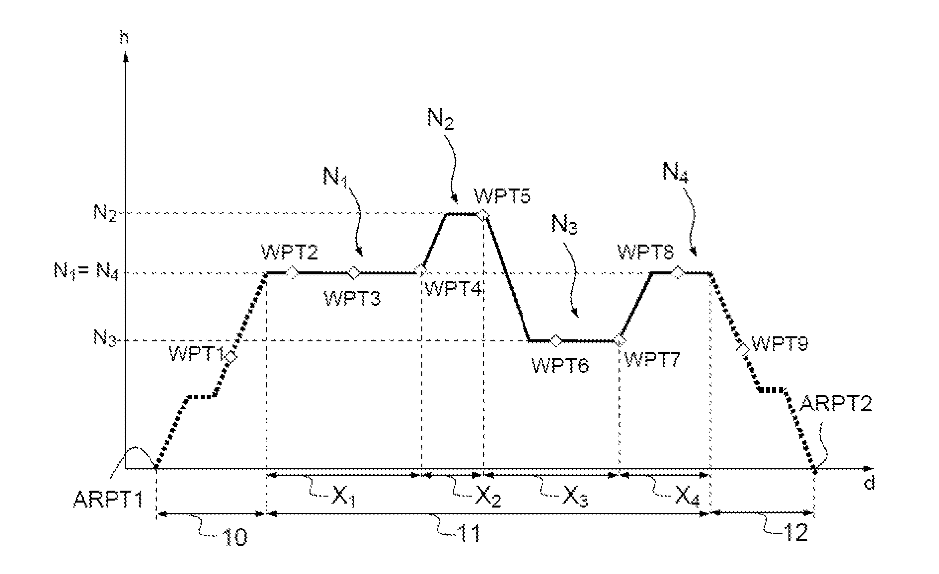
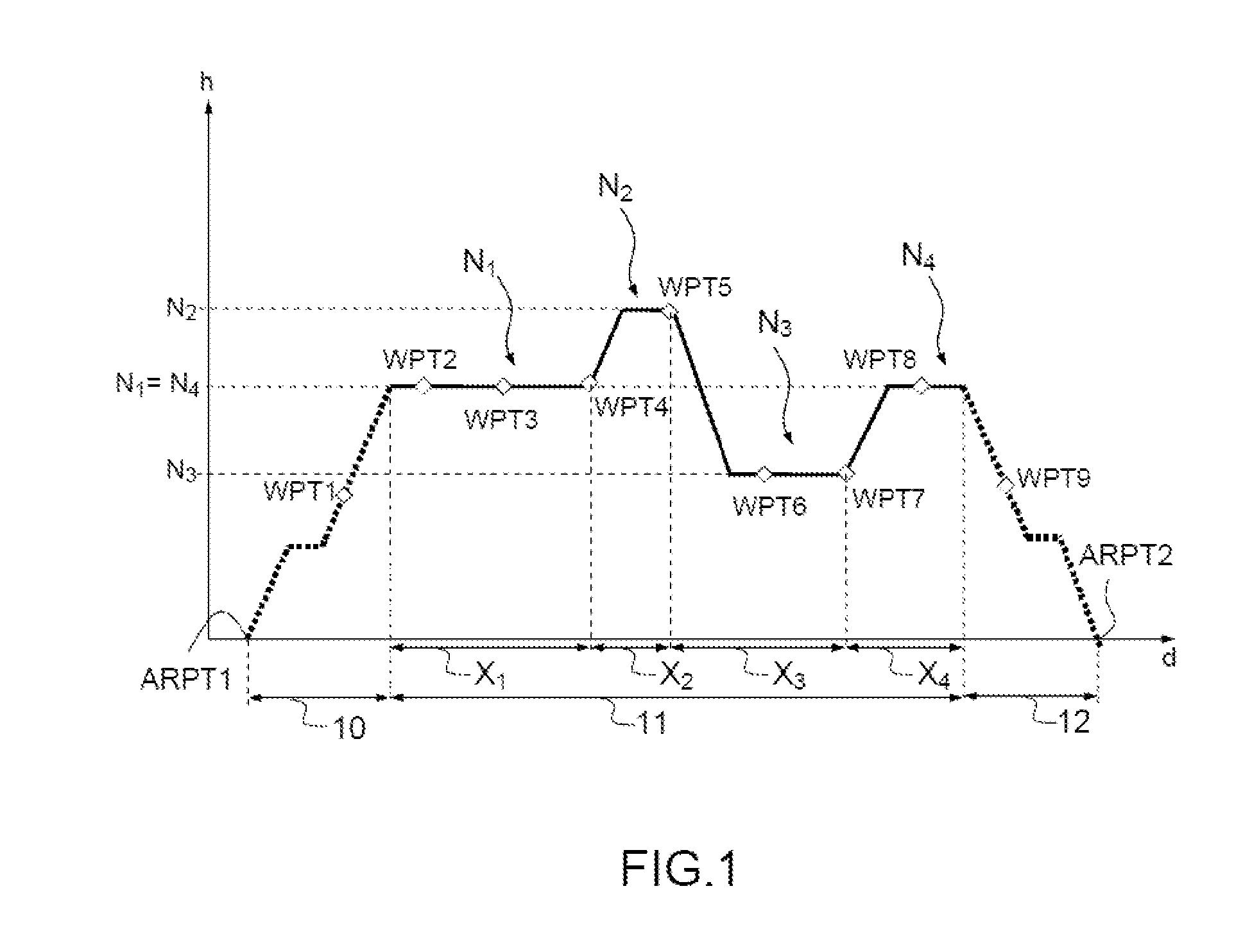
[0057]FIG. 1 illustrates an example of a vertical trajectory profile computed according to the invention. The phase 10 corresponds to the climb phase, the phase 11 to the cruising phase and the phase 12 to the descent phase.

[0058]This vertical profile is computed from a lateral trajectory computed by the FMS and involving an ordered list of waypoints WPT from the flight plan.

[0059]The vertical profile comprises a plurality of altitude levels Ni (commonly called level), i being the index, for example in FIG. 1: N1, N2, N3 and N4. These levels are altitude levels to be reached by the aircraft. Once the level Ni is reached, the aircraft flies at the altitude Ni until the level change point defined by a distance xi, between the level i and the next level i+1.

[0060]The distances xi identify the length of the altitude levels Ni. As an example, xi can correspond to a curvilinear abscissa or, as illustrated in FIG. 1, to the length, distance-wise, of a level Ni: x1 is the length of the leve...


PUM


Abstract

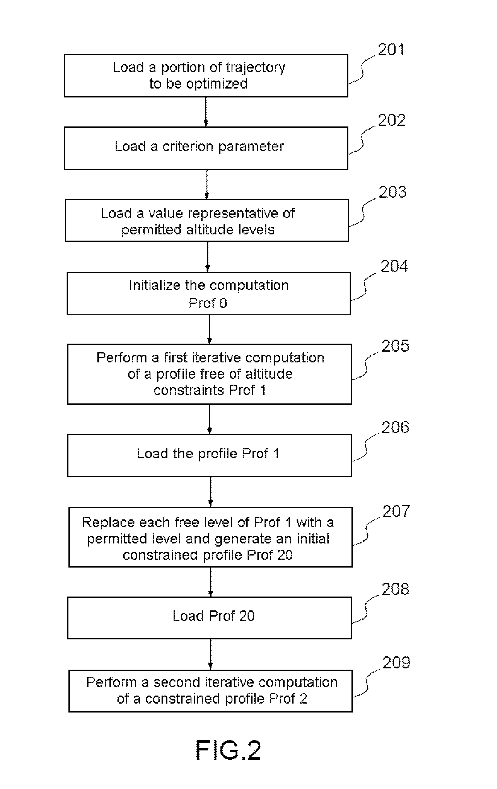
A method for creating a vertical trajectory profile of an aircraft by optimization of a criterion representative of a flight cost, comprises: performing a first iterative computation of a profile free of altitude constraints as long as a condition dependent on the criterion is not reached, replacing each free level of the constraint-free profile with a permitted level so as to generate an initial constrained profile comprising a plurality of permitted levels, and, for each level, an altitude change point and a plurality of speeds, and performing a second iterative computation of a profile in which the altitude levels to be reached remain constant, equal to the initial permitted levels of the initial constrained profile, as long as a condition dependent on the criterion is not reached.

Description

CROSS-REFERENCE TO RELATED APPLICATION[0001]This application claims priority to foreign French patent application No. FR 1300409, filed on Feb. 22, 2013, the disclosure of which is incorporated by reference in its entirety.FIELD OF THE INVENTION[0002]The present invention relates to the field of Flight Management Systems (FMS) or of mission preparation, from the Electronic Flight Bag (OIS / EFB) function.[0003]More particularly, the invention relates to functions of these systems related to the optimization of direct flight operational costs, for example fuel consumption, flight time or CO2 / Nox emissions during the aircraft cruising phase.BACKGROUND[0004]Fuel savings and reducing emissions of certain gases are a major issue for airlines and therefore for pilots. The new taxes on emissions are prompting the airlines to take this issue into consideration. The problem faced is how to assist the crew in saving on fuel and minimizing the emissions by offering it a vertical cruising traject...

Claims


Application Information

Patent Timeline
IPC IPC(8): B64C19/00
CPCB64C19/00G05D1/0005G05D1/0607G01C21/20G08G5/0021G08G5/0034
Inventor LASO-LEON, ENRIQUEAUDOUY, AMANDINEMEULLE, GUILLAUMEROGER, MICHEL
Owner THALES SA
Learn More