This helps you quickly interpret patents by identifying the three key elements:
Problems solved by technology
Method used
Benefits of technology
[0011]In yet another embodiment of this disclosure, a method for securing a valve actuator to a valve assembly includes providing an actuator housing having an actuator axis, a plurality of housing lugs spaced apart around a circumference of the actuator housing, the plurality of housing lugs protruding radially to define a plurality of housing slots therebetween, and a cylinder assembly located within the actuator housing, the cylinder assembly having a horseshoe connector. A valve stem nub of a first portion of a valve stem is located within a horseshoe connector opening of the horseshoe connector so that a lip adjacent to the horseshoe connector opening engages a nub shoulder of the valve stem nub and axial movement of the horseshoe connector c
Problems solved by technology
Some threaded connections between actuators and bonnets and actuators and valve stems currently used in the
Method used
Image
Click on the blue label to locate the original text in one second.
Reading with bidirectional positioning of images and text.
Examples
Embodiment Construction
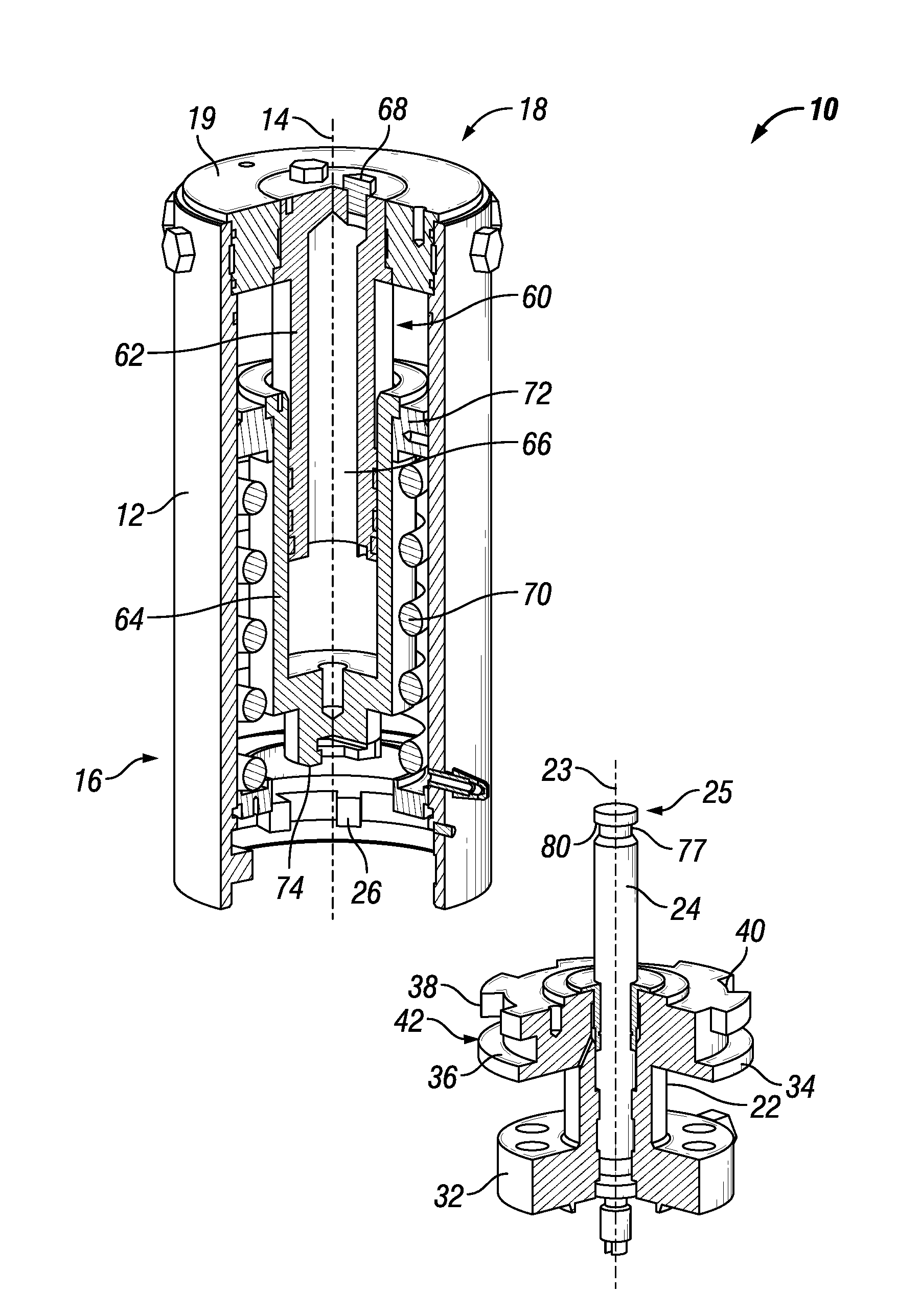
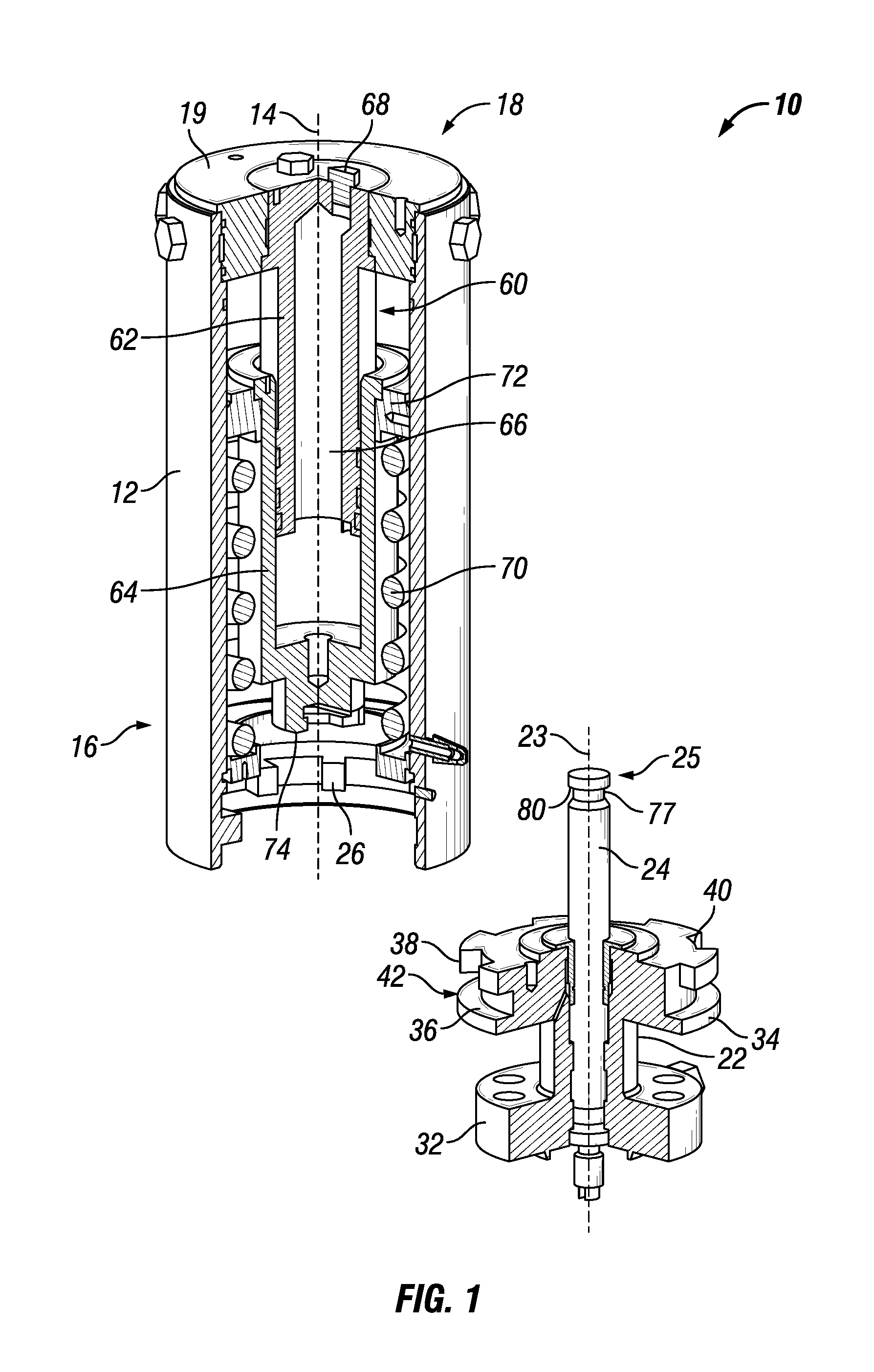
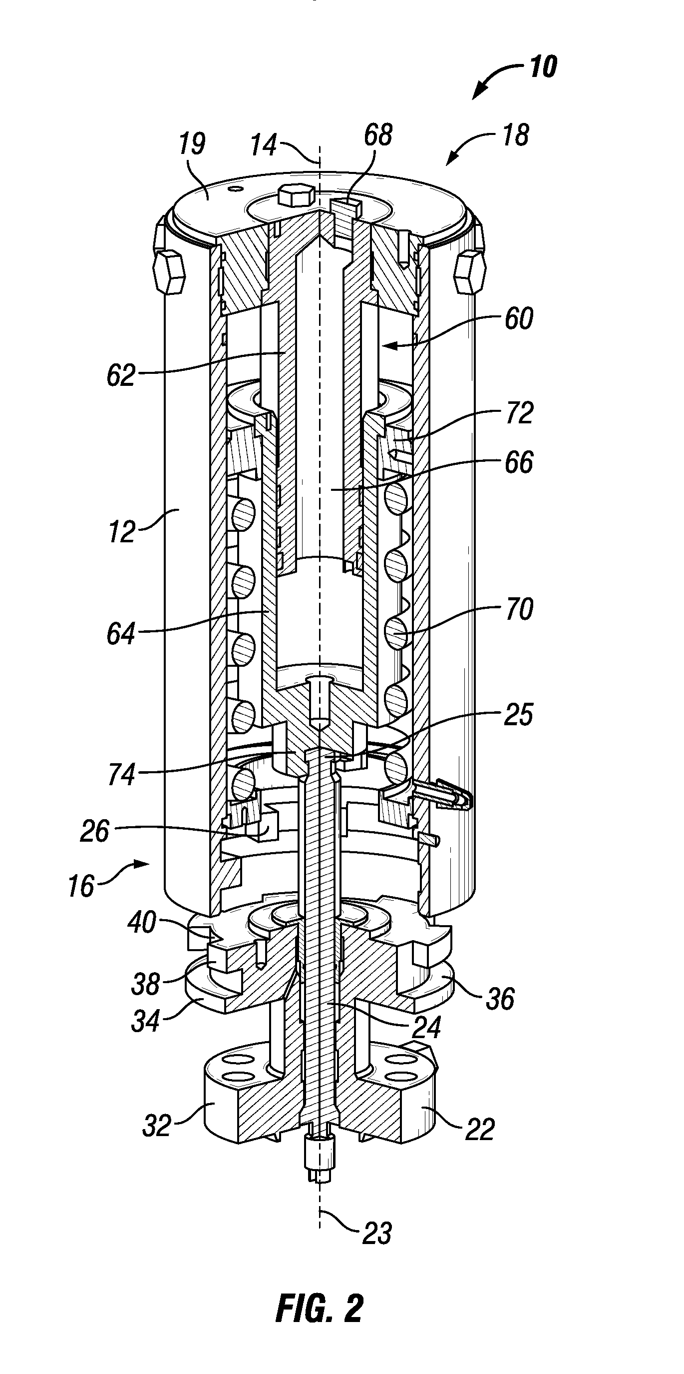
[0021]The method and system of the present disclosure will now be described more fully hereinafter with reference to the accompanying drawings in which embodiments are shown. The method and system of the present disclosure may be in many different forms and should not be construed as limited to the illustrated embodiments set forth herein; rather, these embodiments are provided so that this disclosure will be thorough and complete, and will fully convey its scope to those skilled in the art. Like numbers refer to like elements throughout.
[0022]It is to be further understood that the scope of the present disclosure is not limited to the exact details of construction, operation, exact materials, or embodiments shown and described, as modifications and equivalents will be apparent to one skilled in the art. In the drawings and specification, there have been disclosed illustrative embodiments and, although specific terms are employed, they are used in a generic and descriptive sense onl...
PUM
Abstract
A system for securing a valve actuator to a valve assembly includes an actuator housing with a plurality of housing lugs protruding radially. A cylinder assembly is located within the actuator housing and has a horseshoe connector to engage a valve stem nub of a valve stem and transfer axial movement of the horseshoe connector to axial movement of the valve stem. A bonnet has a plurality of bonnet lugs protruding radially from the bonnet to define a plurality of bonnet slots therebetween, wherein each of the plurality of housing lugs are sized to pass axially through a respective one of the plurality of bonnet slots when the actuator housing is in a released position, the actuator housing being rotatable to a locked position such that the plurality of bonnet lugs prevent axial movement of the actuator housing in at least one direction.
Description
CROSS REFERENCE TO RELATED APPLICATION[0001]This application claims priority to and the benefit of co-pending U.S. Provisional Application Ser. No. 62 / 172,544, filed Jun. 8, 2015, titled “Compound Express Actuator Connection,” the full disclosure of which is hereby incorporated herein by reference in its entirety for all purposes.[0002]This application is also a continuation in part of co-pending U.S. application Ser. No. 14 / 949,324, titled “No-Bolt Security Latching System,” filed Nov. 23, 2015, which is a continuation in part of U.S. application Ser. No. 13 / 832,884, now U.S. Pat. No. 9,212,758, titled “Quick Connect Valve Actuator,” filed Mar. 15, 2013, which claims priority to U.S. Provisional Patent Application No. 61 / 747,479, titled “Quick Connect Valve Actuator,” filed on Dec. 31, 2012, the disclosure of each which is incorporated herein by reference in its entirety.BACKGROUND[0003]1. Field of the Disclosure[0004]This invention relates in general to actuators for actuating val...
Claims
Application Information
Patent Timeline
Application Date:The date an application was filed.
Publication Date:The date a patent or application was officially published.
First Publication Date:The earliest publication date of a patent with the same application number.
Issue Date:Publication date of the patent grant document.
PCT Entry Date:The Entry date of PCT National Phase.
Estimated Expiry Date:The statutory expiry date of a patent right according to the Patent Law, and it is the longest term of protection that the patent right can achieve without the termination of the patent right due to other reasons(Term extension factor has been taken into account ).
Invalid Date:Actual expiry date is based on effective date or publication date of legal transaction data of invalid patent.