

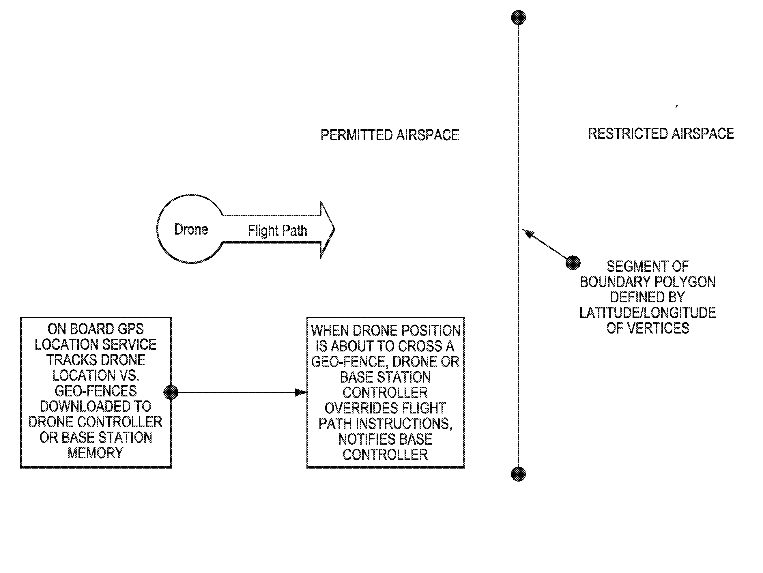
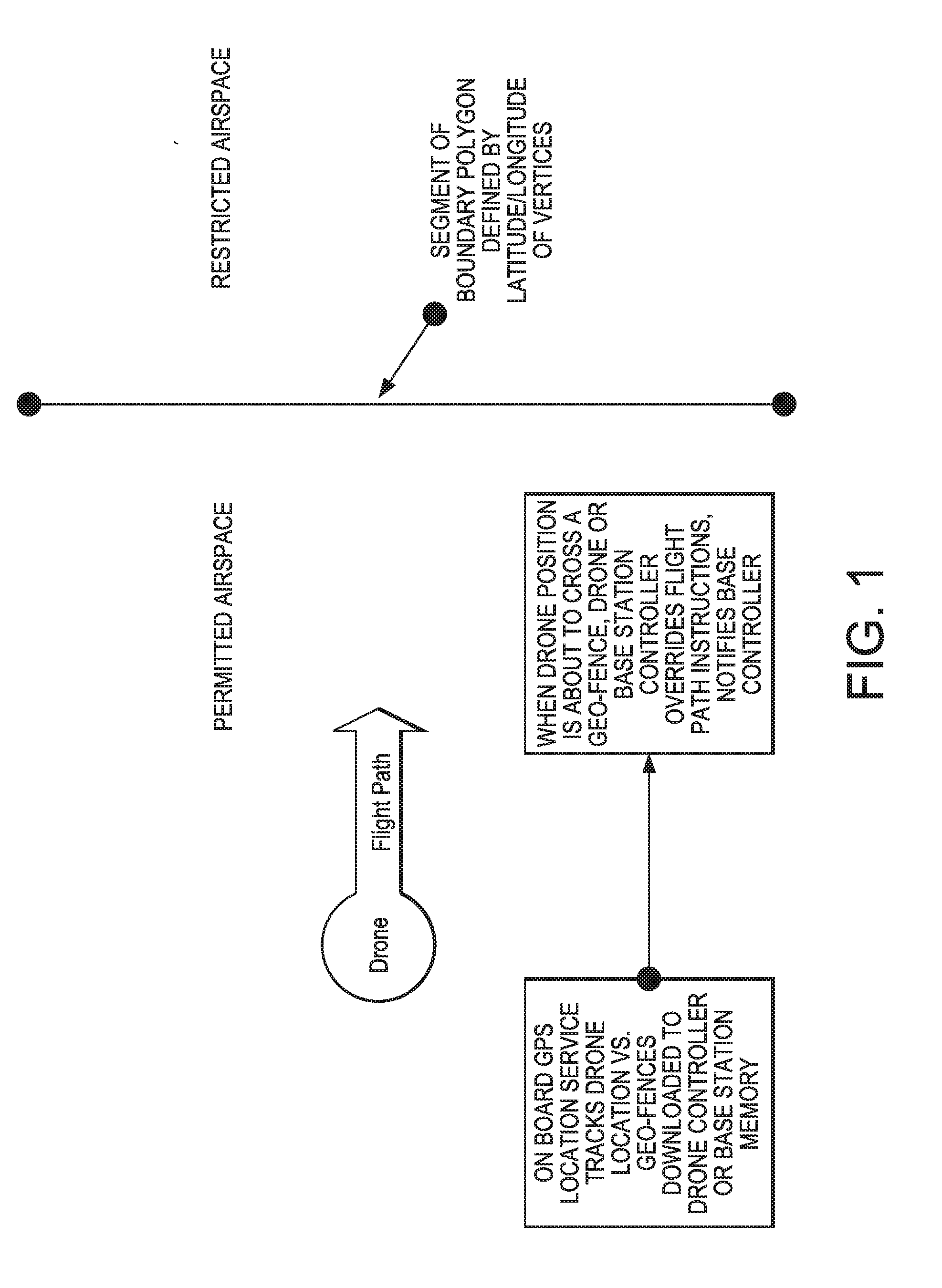
Method for keeping drones within a designated boundary
a technology for drones and designated boundaries, applied in vehicle position/course/altitude control, process and machine control, instruments, etc., can solve the problems of restricted altitude and airspace, drone operators may not be able to see that their remote controlled drones have crossed a boundary into restricted airspace,
- Summary
- Abstract
- Description
- Claims
- Application Information
AI Technical Summary
Benefits of technology
Problems solved by technology
Method used
Image

Examples
Embodiment Construction
[0011]The following detailed description is presented to enable any person skilled in the art to make and use the invention. For purposes of explanation, specific details are set forth to provide a thorough understanding of the present invention. However, it will be apparent to one skilled in the art that these specific details are not required to practice the invention. Descriptions of specific applications are provided only as representative examples. Various modifications to the preferred embodiments will be readily apparent to one skilled in the art, and the general principles defined herein may be applied to other embodiments and applications without departing from the scope of the invention. The present invention is not intended to be limited to the embodiments shown, but is to be accorded the widest possible scope consistent with the principles and features disclosed herein.
[0012]This invention solves the problem of keeping drones within a boundary by using the inventor's Tra...
PUM
 Abstract
Description
Claims
Application Information