Resin sealing apparatus and resin sealing method

a sealing apparatus and resin technology, applied in the direction of electrical apparatus, domestic applications, other domestic objects, etc., can solve the problems of increasing the size of the sealing apparatus and the size of the pressing mechanism

Active Publication Date: 2016-09-29
TOWA
View PDF2 Cites 3 Cited by
  • Summary
  • Abstract
  • Description
  • Claims
  • Application Information

AI Technical Summary

Benefits of technology

[0008]An object of the present invention is to provide a resin sealing apparatus and a resin sealing method t

Problems solved by technology

First, this may cause deformation, break and the like of a wire used to electrically connect the component to be sealed and the subst

Method used


Image

  • Resin sealing apparatus and resin sealing method
  • Resin sealing apparatus and resin sealing method
  • Resin sealing apparatus and resin sealing method

Examples


first embodiment

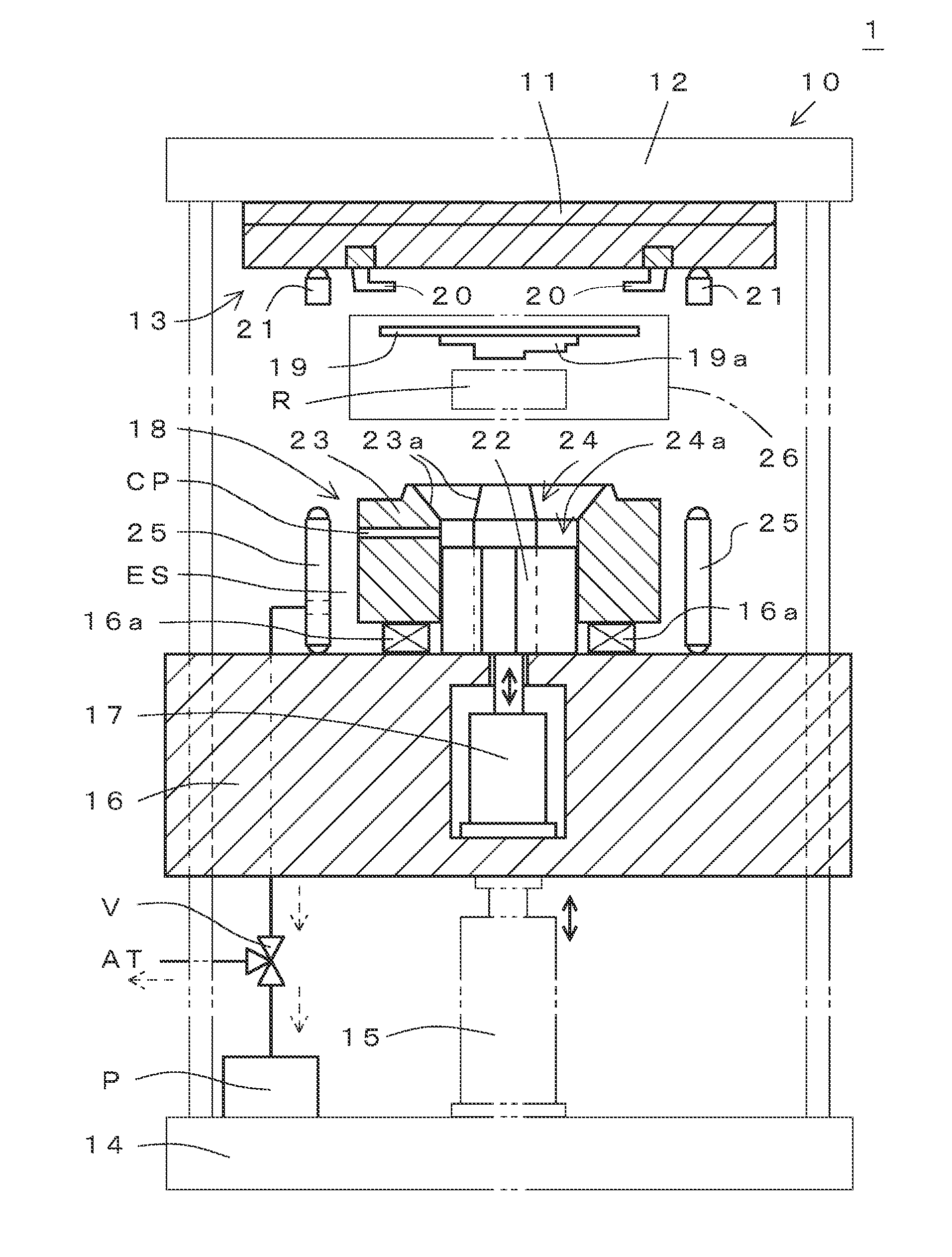
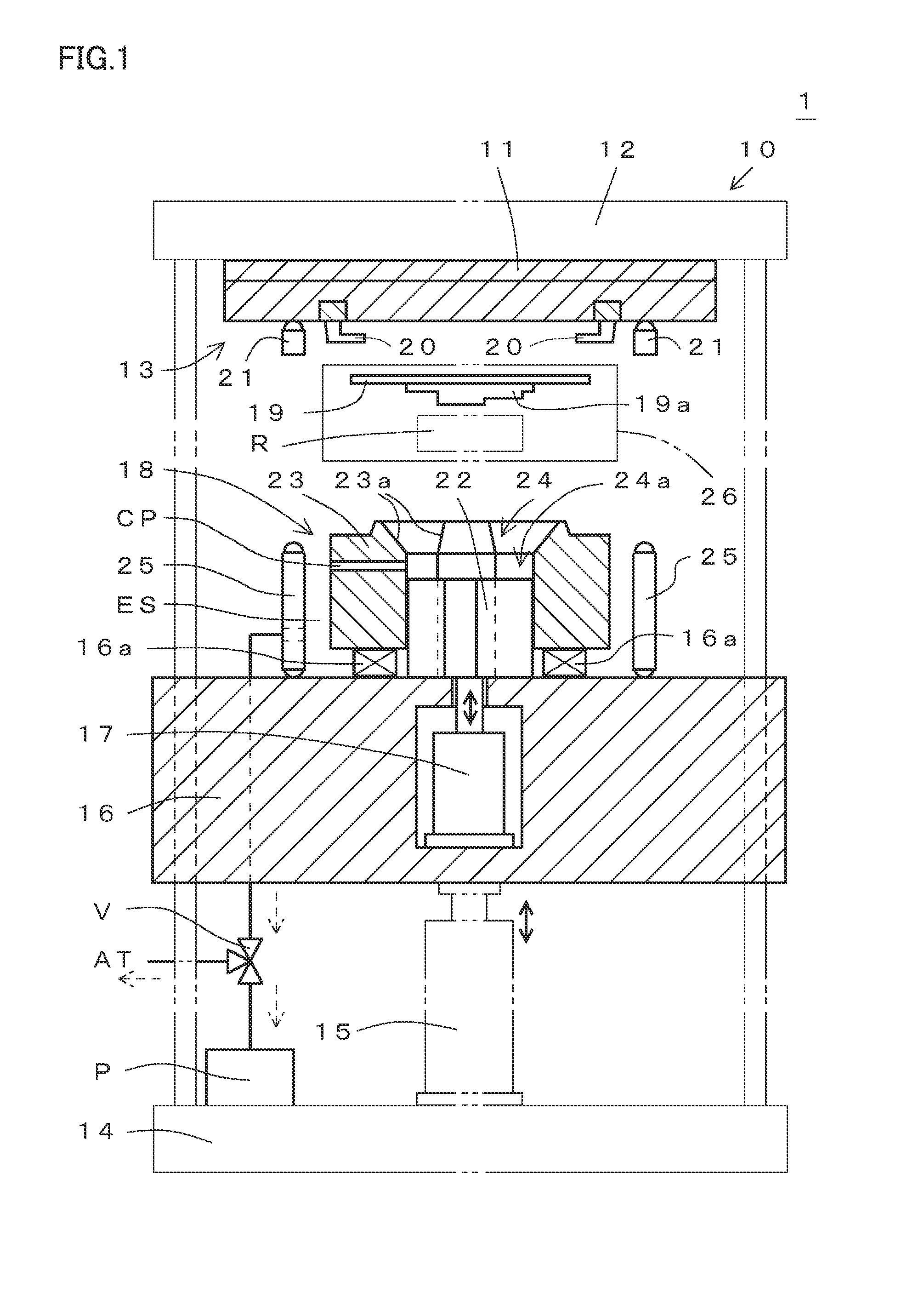
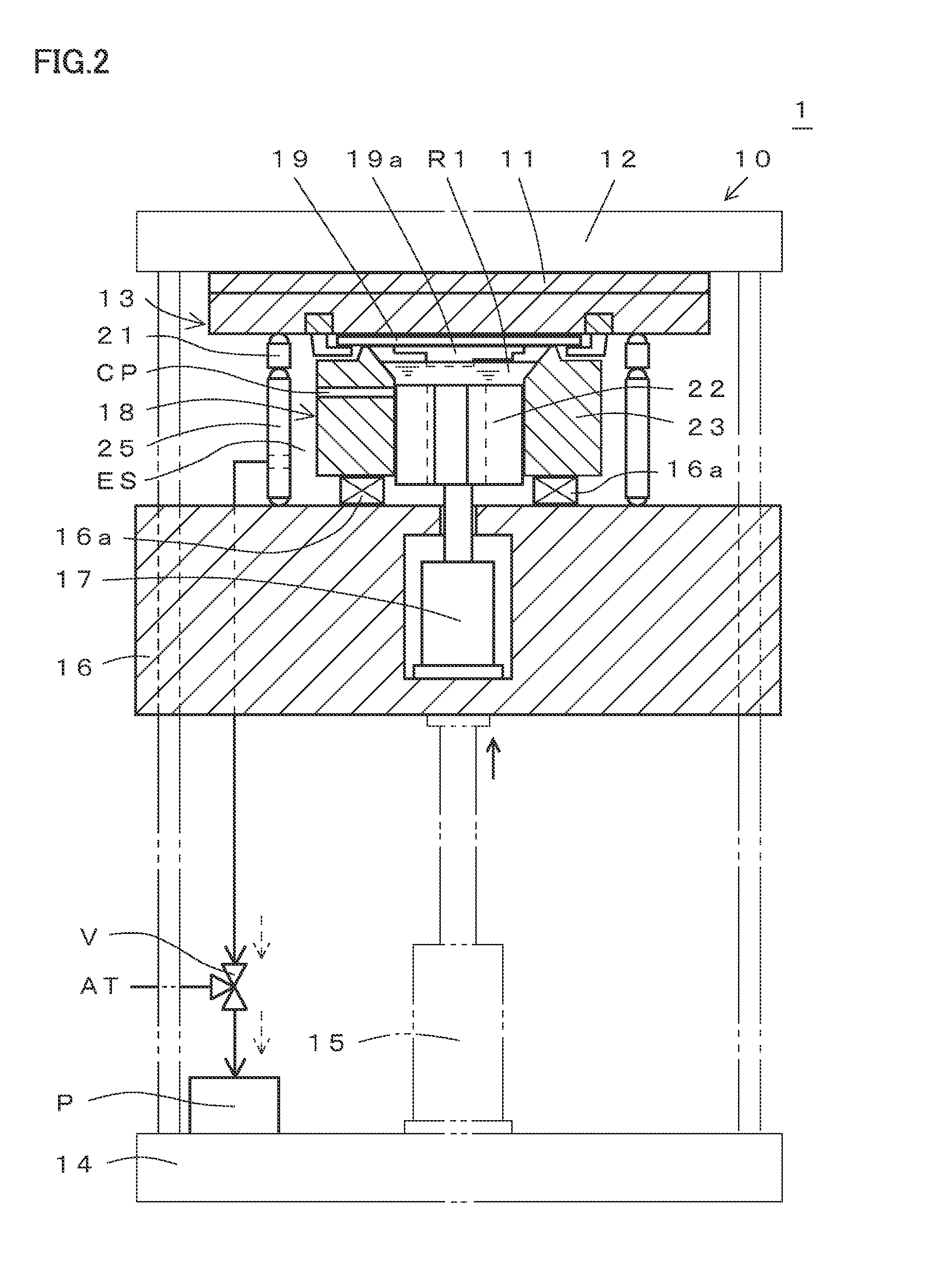
[0109]A first embodiment of a resin sealing apparatus and a resin sealing method according to the present invention will be described with reference to FIGS. 1 to 8C. For the sake of clarity, any drawings throughout the specification are schematic and omission or exaggeration is made as appropriate. As shown in FIGS. 1 to 5B, a resin sealing apparatus 1 according to the present invention has a molding module 10. As described below (refer to FIG. 12), molding module 10 can be attached to and separated from another module (such as a material receiving module and another molding module 10). The present invention is not limited to such resin sealing apparatus having molding module 10.

[0110]Molding module 10 includes an upper mold base 11, and upper mold 13 attached to a lower surface of a fixed platen 12 with upper mold base 11 interposed therebetween. Molding module 10 includes a base 14, a vertical drive mechanism 15 attached onto base 14, and a movable platen 16 provided to be capabl...

second embodiment

[0157]A second embodiment of the resin sealing apparatus and the resin sealing method according to the present invention will be described with reference to FIGS. 9 to 10. In the first embodiment, vertical drive mechanism 15 for driving side surface member 23 is attached to base 14. Vertical drive mechanism 17 for driving bottom surface member 22 is attached to movable platen 16 raised and lowered by vertical drive mechanism 15. The present embodiment describes another configuration in which vertical drive mechanism 15 and vertical drive mechanism 17 are provided separately. The components in the present embodiment that are substantially the same as those in the first embodiment have been described in the first embodiment. The common components in the two embodiments are denoted by the same reference characters and description thereof will not be repeated.

[0158]Differences between the present embodiment and the first embodiment will be described. As shown in FIGS. 9 to 10, lower mol...

third embodiment

[0162]A third embodiment of the resin sealing apparatus and the resin sealing method according to the present invention will be described with reference to FIGS. 11A and 11B. The present embodiment is related to the manner of using communicating path CP shown in FIGS. 1 to 3 to allow a gap 40 between the inner bottom surface of the cavity (the upper end surface of bottom surface member 22) and the end surface of sealing resin R2 to communicate with external space ES which is a space outside the mold.

[0163]FIG. 11A shows a position of communicating path CP shown in FIGS. 1 to 3. As shown in FIG. 11A, in side surface member 23, communicating path CP is provided at a position lower than a position corresponding to the thickness of sealing resin R2 to be molded (refer to FIG. 5B) with respect to the upper surface of side surface member 23. An opening 42 of communicating path CP is formed in an inner circumferential surface 41 (surface extending downwardly from inner circumferential surf...


PUM

PropertyMeasurementUnit
Pressureaaaaaaaaaa
Circumferenceaaaaaaaaaa

Abstract

A lower mold has a bottom surface member and a side surface member. An upper end surface of the bottom surface member forms an inner bottom surface of a cavity and has a planar shape corresponding to an unusual planar shape of a sealing resin. A substrate is disposed on a mold surface of an upper mold such that a component to be sealed attached to the substrate faces downward, and the cavity is filled with a fluid resin. The upper mold and the lower mold are clamped, and the component is immersed in the fluid resin. The bottom surface member is raised, and the fluid resin is pressed at a prescribed resin pressure and cured to form the sealing resin. The bottom surface member and the side surface member are moved relatively, and thereby, a molded product is released from a mold surface of the lower mold.

Description

BACKGROUND OF THE INVENTION[0001]1. Field of the Invention[0002]The present invention relates to a resin sealing apparatus and a resin sealing method for providing resin sealing for a component to be sealed attached onto a substrate by a sealing resin.[0003]2. Description of the Background Art[0004]In order to form a molded product, a cavity formed by a space filled with a fluid resin is formed in a mold for resin sealing. A so-called film molding method is widely known, in which a mold surface of a mold is covered with a mold release film and thus a resin molded product molded within a cavity is easily separated from the mold surface (refer to, for example, Japanese Patent Laying-Open No. 08-142109). According to this film molding method, the die surface (mold surface) of the mold including the cavity is covered with the release film (mold release film) that is easily separated from the molding die (mold) and the molding resin (sealing resin). The mold is clamped, and thereby, a le...

Claims


Application Information

Patent Timeline
IPC IPC(8): H01L21/67B29C43/56B29C43/18
CPCH01L21/67126B29C43/18B29L2031/3406B29C2043/182B29C2043/561B29C43/56B29C45/2602B29L2031/34B29L2031/3425B29C33/42B29C33/44B29C43/021B29C43/36B29C43/361B29C43/50H01L21/565B29C2043/181B29C2043/565
Inventor ONISHI, YOHEITAKA, TAKEAKI
Owner TOWA
Why Eureka
Try Eureka