Light emitting device
a technology of light emitting device and light guide plate, which is applied in the direction of planar/plate-like light guide, instruments, optics, etc., can solve the problems of uneven luminance, high manufacturing cost of light guide plate, and insufficient light emitted by the light emitting element disposed in the package, so as to suppress uneven luminance.
- Summary
- Abstract
- Description
- Claims
- Application Information
AI Technical Summary
Benefits of technology
Problems solved by technology
Method used
Image
Examples
first embodiment
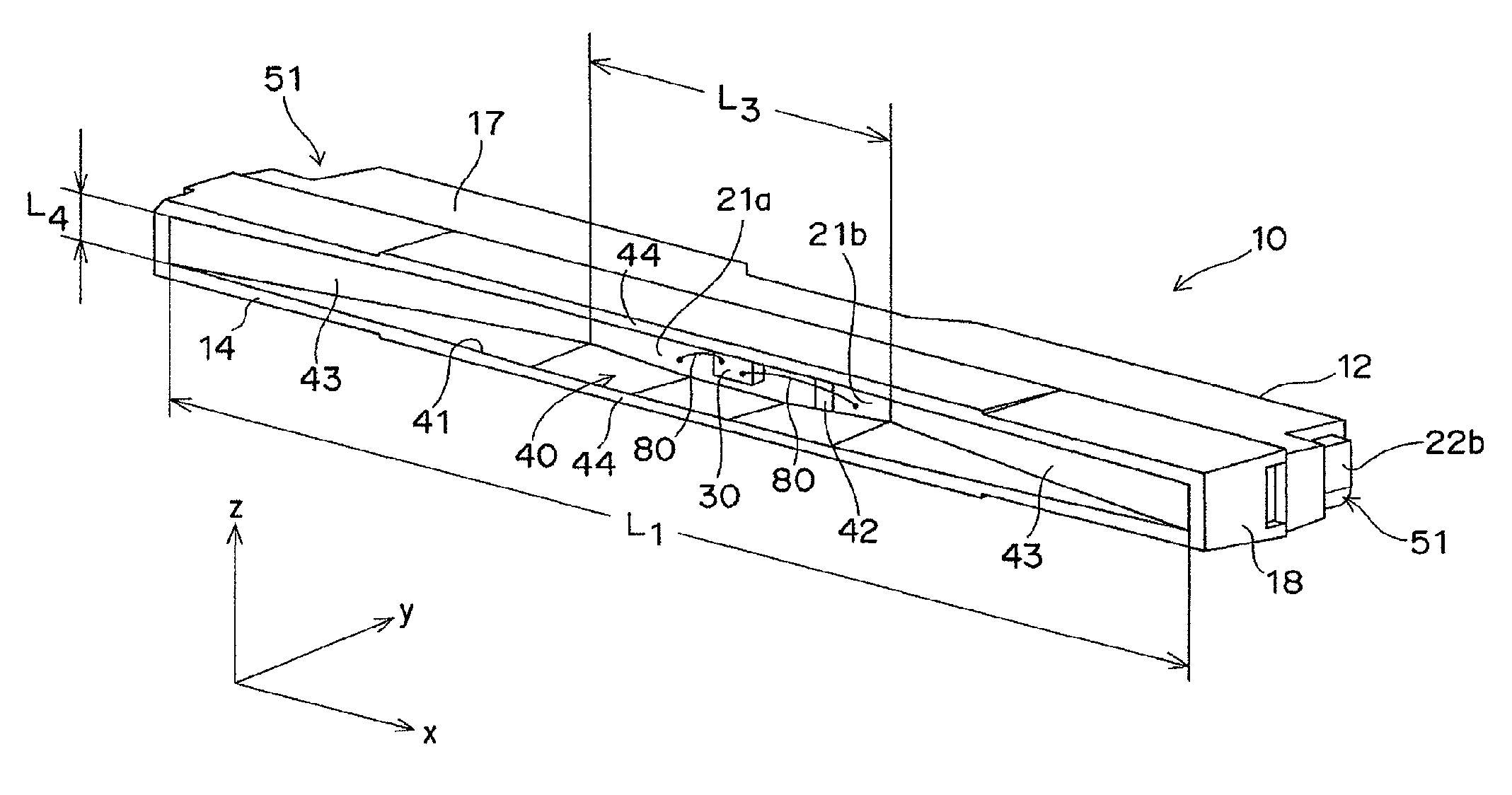
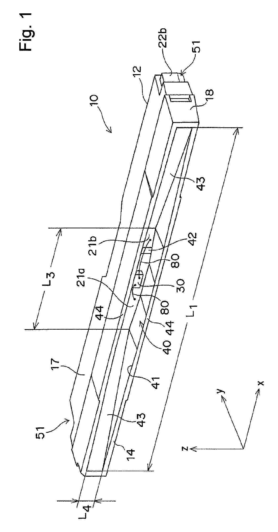
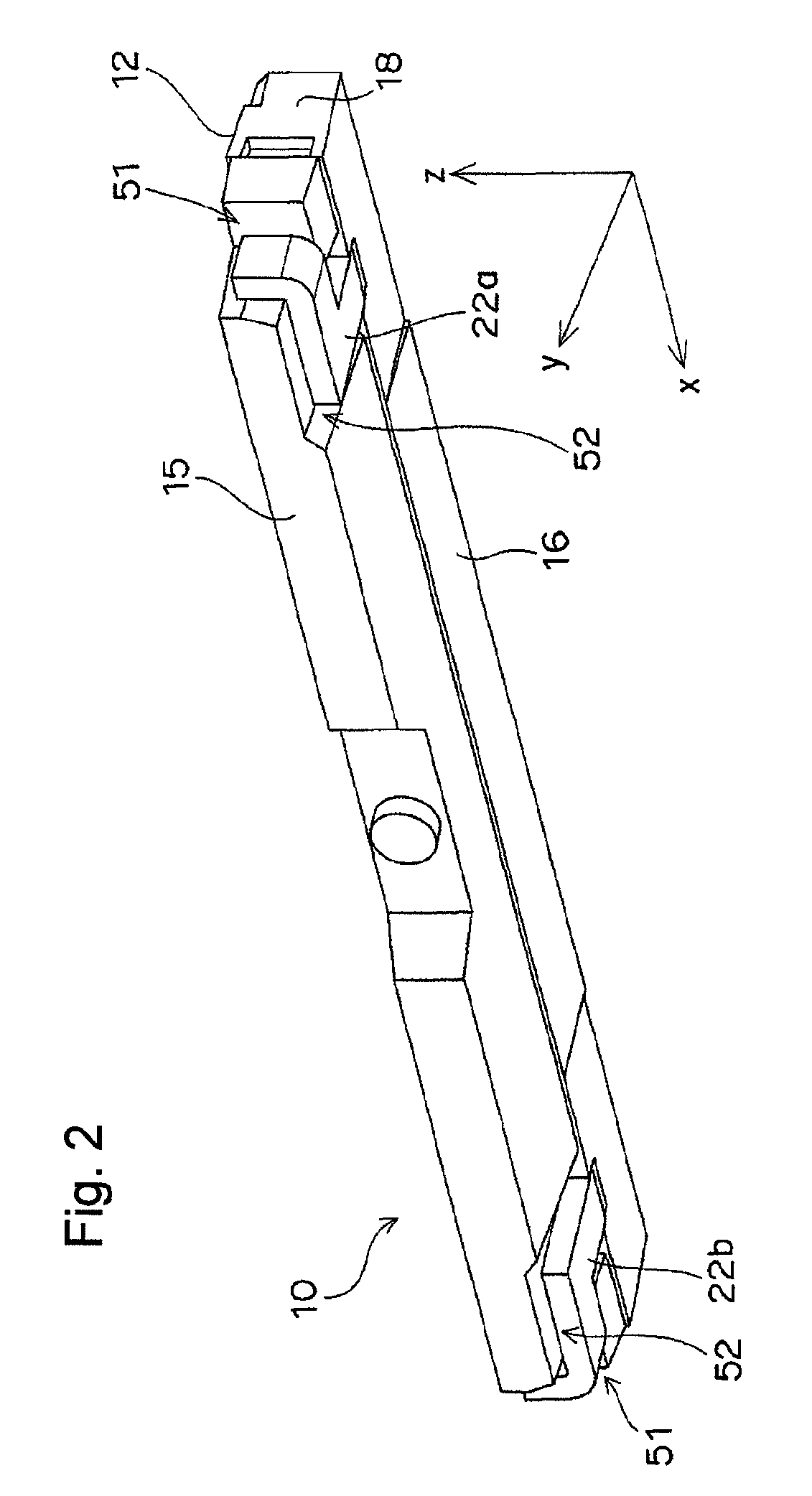
[0030]FIG. 1 and FIG. 2 show a side-view type light emitting device 10 according to this embodiment. FIG. 3 to FIG. 6 show such a state as a package 12 used in the light emitting device 10 of this embodiment is cut off from a lead frame 20. The light emitting device 10 comprises the package 12 that has a recess 40, with a light emitting element 30 mounted in the recess 40. Lead electrodes 21a, 21b are exposed as connection terminals on the bottom surface 42 of the recess 40, with part of the lead electrodes 21a, 21b penetrating through the package 12 to protrude to the outside. The light emitting element 30 and the lead electrodes 21a, 21b are connected to each other by means of electrically conductive wires 80.
[0031]The recess 40 of the package 12 opens in one surface that serves as a light emitting surface 14, and the opening 41 is elongated in one direction (x direction). Among inner side surfaces of the recess 40, the side surfaces on both sides in the longitudinal direction (x ...
second embodiment
[0065]In the first embodiment described above, the step 52 (refer to FIG. 2) is formed in the mounting surface 16 of the package 12 in such a manner as the external terminals 22a, 22b can be accommodated therein when the external terminals 22a, 22b of the lead electrodes 21a, 21b are bent toward the back surface 15. The step 52 is not formed on the side of the light emitting surface 14 beyond the position where the external terminals 22a, 22b protrude from the package 12.
[0066]This embodiment is difference from the first embodiment in that the step 52 is formed also on the side of the light emitting surface 14 beyond the position where the external terminals 22a, 22b protrude from the package 12 (refer to FIG. 10). With other respects, this embodiment is the same as the first embodiment.
[0067]The step 52 is located inward from the mounting surface 16. The lead electrodes 21a, 21b protrude beyond the position of the step 52 of the mounting surface 16. That is, a boundary portion 53 b...
example 1
[0069]Luminance distribution at the center was simulated for the light emitting device 10 shown in FIG. 1. The “luminance distribution at the center” as used herein means the luminance distribution along a line that passes the center of the package 12 in the direction perpendicular to the longitudinal direction of the package 12 (z direction), and extends in the longitudinal direction of the package 12 (x direction).
[0070]Dimensions of four kinds of the light emitting device 10 (Examples 1 to 4) that were simulated are shown in Table 1.
[0071]
TABLE 1Example 1Example 2Example 3Example 4Length L1 of the opening4.764.765.765.76in x direction (mm)Length L2 of the inclined1.611.642.092.12surface (mm)Length L3 of the bottom1.71.71.71.7surface (mm)Length L4 of the opening0.290.290.290.29in z direction (mm)Depth d of the recess0.50.60.50.6(mm)Angle θ between the two143.8137.2152.3147.1inclined surfaces(degrees)
[0072]For the purpose of comparison, luminance distribution at the center was simu...
PUM
 Abstract
Description
Claims
Application Information
 - R&D
- Intellectual Property
- Life Sciences
- Materials
- Tech Scout
- Unparalleled Data Quality
- Higher Quality Content
- 60% Fewer Hallucinations
Browse by: Latest US Patents, China's latest patents, Technical Efficacy Thesaurus, Application Domain, Technology Topic, Popular Technical Reports.
© 2025 PatSnap. All rights reserved.Legal|Privacy policy|Modern Slavery Act Transparency Statement|Sitemap|About US| Contact US: help@patsnap.com


