Stator of rotary machine

a rotary machine and rotating shaft technology, applied in the direction of windings, conductor shapes/forms/construction, magnetic circuit stationary parts, etc., can solve the problems of difficult to make the coil end small, the terminal voltage cannot be easily changed, etc., to improve the cooling effect, reduce the coil end size, and prevent the occurrence of circulating current

Active Publication Date: 2021-07-06
MEIDENSHA ELECTRIC MFG CO LTD
View PDF25 Cites 1 Cited by
  • Summary
  • Abstract
  • Description
  • Claims
  • Application Information

AI Technical Summary

Benefits of technology

[0034]In accordance with the stator of the rotary machine according to the present invention, the unit coil is formed by alternately and concentrically arranging the segments in the radial direction with a plurality of slot pitches different from each other. This makes it possible to arrange another segment on the inner side in the axial direction of one segment. As compared with conventional unit coils, it is possible to form a unit coil by making the segments dense. This makes it possible to decrease the coil end size. Furthermore, in the case of directly cooling the coil ends with liquid, it becomes possible to sufficiently spread coolant throughout the coil ends due to making the segments dense, thereby improving the cooling effect. Furthermore, it becomes possible to select series wiring or parallel wiring by changing the unit coil's connection relation to be formed by the segment arrangement, even if the segment arrangement is the same. In addition, even in the case of making it into parallel wiring, it is possible to prevent the occurrence of circulating current.

Problems solved by technology

Thus, there has been a problem that the terminal voltage cannot be changed easily.
Therefore, there has been a problem that it is difficult to make the coil ends small.

Method used


Image

  • Stator of rotary machine
  • Stator of rotary machine
  • Stator of rotary machine

Examples


embodiments

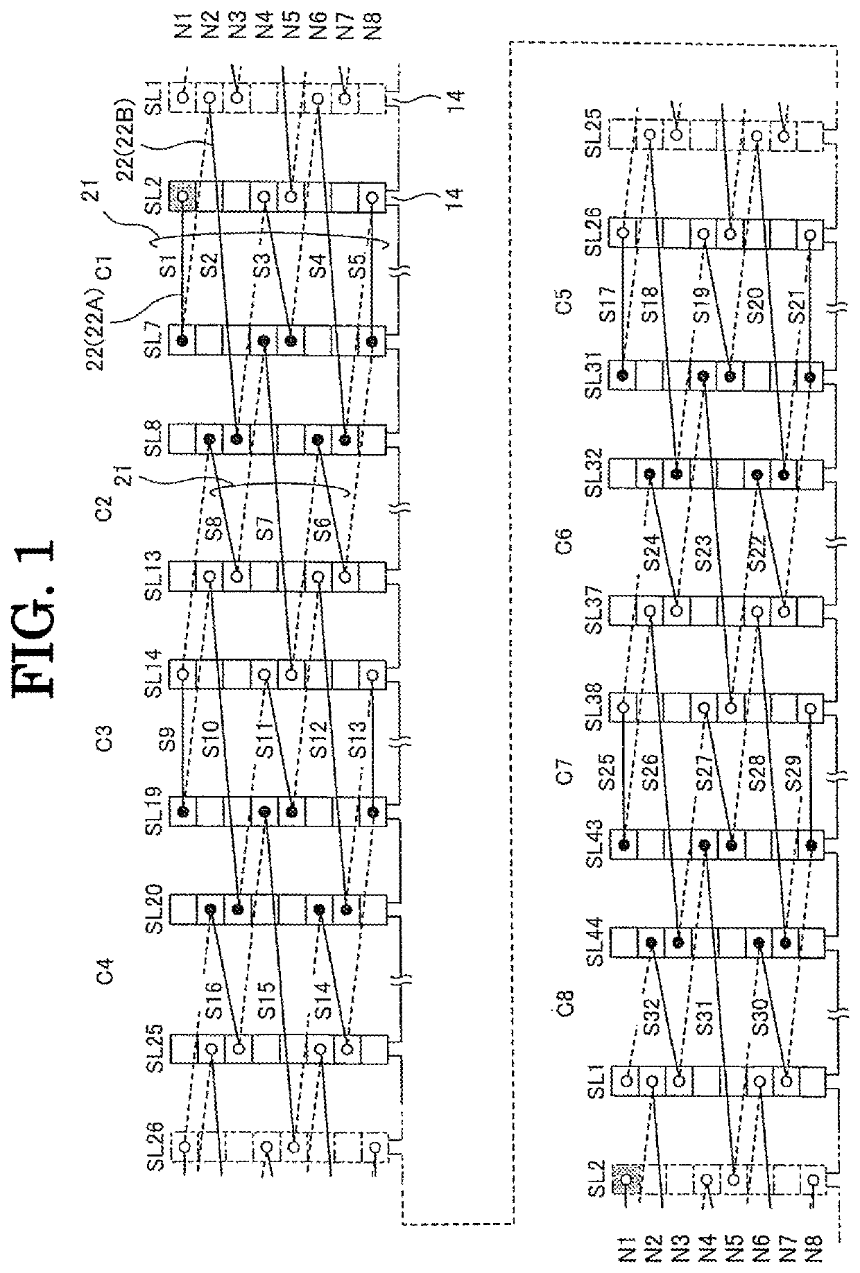
[0043]Using FIG. 1 to FIG. 6, the stator of the electric machine according to one embodiment of the present invention is explained in detail. The structure of the stator of the rotary machine according to the present embodiment is generally similar to the above-mentioned rotary machine stator 10 shown in FIG. 7 except each phase winding wire arrangement. Therefore, in the following explanation, members showing functions similar to the above-mentioned members shown in FIG. 7 are designated by the same signs, and the repetitive explanations are omitted.

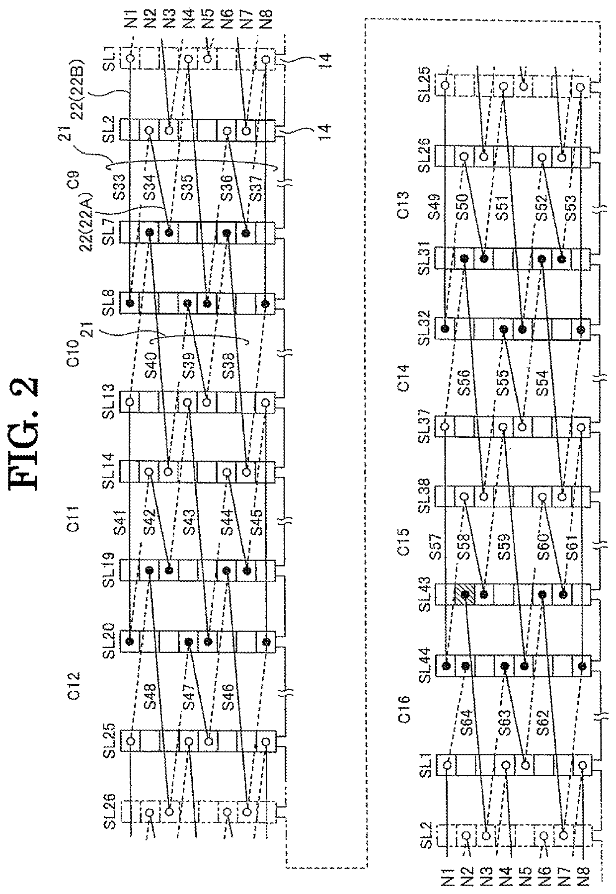
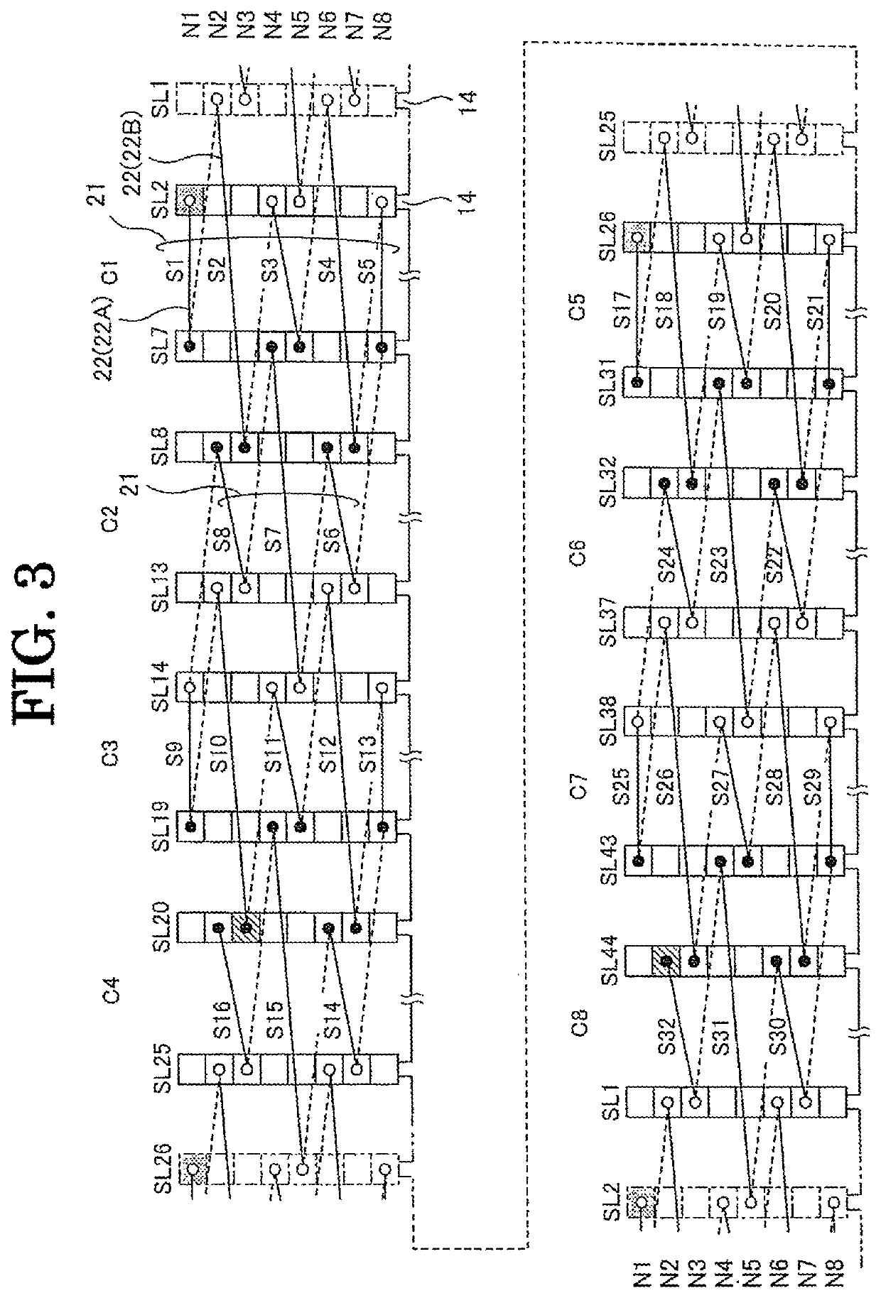
[0044]FIG. 1 and FIG. 2 show a segments 22 arrangement example in the case of constituting U-phase winding by connecting U1 phase and U2 phase as partial windings in series. FIG. 1 shows U1 phase arrangement, and FIG. 2 shows U2 phase arrangement. Furthermore, FIG. 3 and FIG. 4 show a segments 22 arrangement example in the case of constituting U-phase winding by connecting U1 phase to U4 phase as partial windings in parallel. FIG. 3 sho...


PUM


Abstract

In order to provide a rotary machine's stator that is capable of reducing the size of the coil ends and using a plurality of voltages without changing the winding arrangement, it is made to include a stator core (12) having a plurality of slots (14) provided along the circumferential direction, segments (22) that are composed of rectangular wires and received in the slots (14), and a distributed winding wire that is formed by arranging unit coils (21), each of which is made up of a plurality of the segments (22) disposed along the radial direction, in the circumferential direction of the stator core (12), and is made to form the unit coil (21) by connecting the segments (22) that are alternately and concentrically arranged in the radial direction with a plurality of slot pitches that are different from each other.

Description

TECHNICAL FIELD[0001]The present invention relates to a stator of a rotary machine.BACKGROUND ART[0002]The following Patent Publication 1 discloses a rotary machine for high-voltage vehicles, with a sequentially joined-segment stator coil, which enables to adjacently position a plurality of the same phase slots and to achieve the voltage increase of the rotary machine by increasing the number of turns while suppressing accompanying adverse effects, by providing a plurality of the same phase, adjacent slots and providing special segments and special U-phase segments, which are different from normal segments (9 slot pitch) as segments and have slot pitches different from each other.[0003]Furthermore, as shown in FIG. 7, the following Patent Publication 2 discloses that, in a rotary electric machine stator 10 composed of a stator core 12 prepared by stacking a plurality of annular electromagnetic steel plates and three-phase winding wires 20 to be wound about the stator core 12, a wind...

Claims


Application Information

Patent Timeline
Patent Type & Authority Patents(United States)
IPC IPC(8): H02K3/28H02K1/16
CPCH02K3/28H02K1/16H02K3/12
Inventor SUWAZONO, TAKESHI
Owner MEIDENSHA ELECTRIC MFG CO LTD
Why Eureka
Try Eureka