Spraying tube device and heat exchanger using the same

a technology of spraying tube and heat exchanger, which is applied in the direction of indirect heat exchangers, refrigeration components, lighting and heating apparatus, etc., can solve the problem of reducing the amount of holding gas, and achieve the effect of large pitch distance of nail portions

Active Publication Date: 2016-04-19
KAWASAKI HEAVY IND LTD
View PDF23 Cites 2 Cited by
  • Summary
  • Abstract
  • Description
  • Claims
  • Application Information

AI Technical Summary

Benefits of technology

[0018]The spraying tube device or heat exchanger of the present invention includes the uniformizing structure configured to uniformize in the tube axis direction the distribution of the spray solution flowing downward on the outer surface of the spraying tube. Therefore, even if the amount of spray solution is large, the medium can be uniformly sprayed. In addition, since the width of the cutout portion is set to be larger than the width of the nail portion, the spray solution is prevented from scattering through the cutout portions to the outside, and the spray solution flows along the nail portions to flow downward to the spraying tube in the form of rain drops. At this time, since the width of the cutout portion is large, the pitch distance of the nail portions also becomes large. Therefore, the liquid droplets from the adjacent nail portions are prevented from contacting each other and flowing downward in the form of a waterfall-like line, and the solution can adequately spread on the spraying tube.

Problems solved by technology

However, since such a low boiling point gas is expensive, there is a demand to reduce a holding gas amount as much as possible.

Method used


Image

  • Spraying tube device and heat exchanger using the same
  • Spraying tube device and heat exchanger using the same
  • Spraying tube device and heat exchanger using the same

Examples


Embodiment Construction

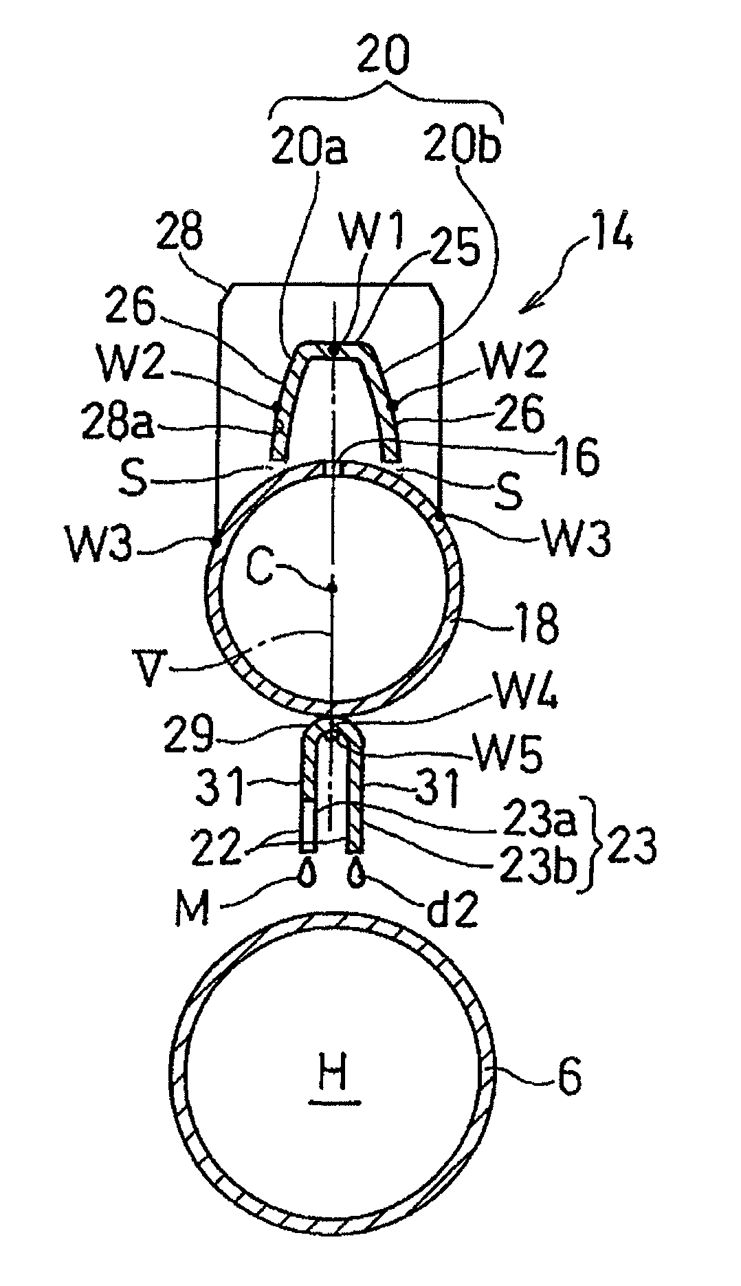
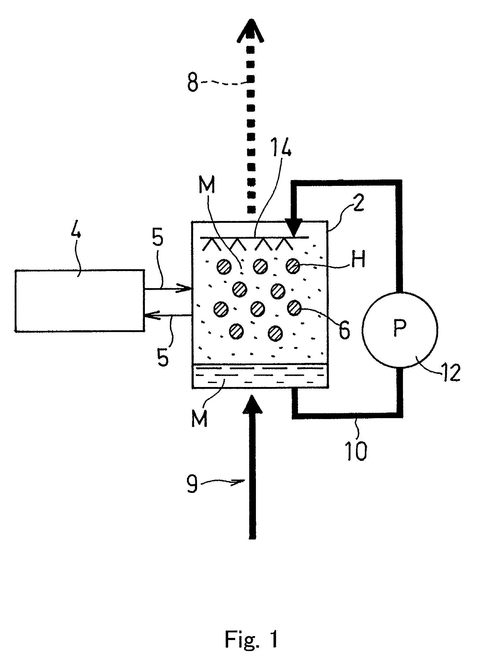
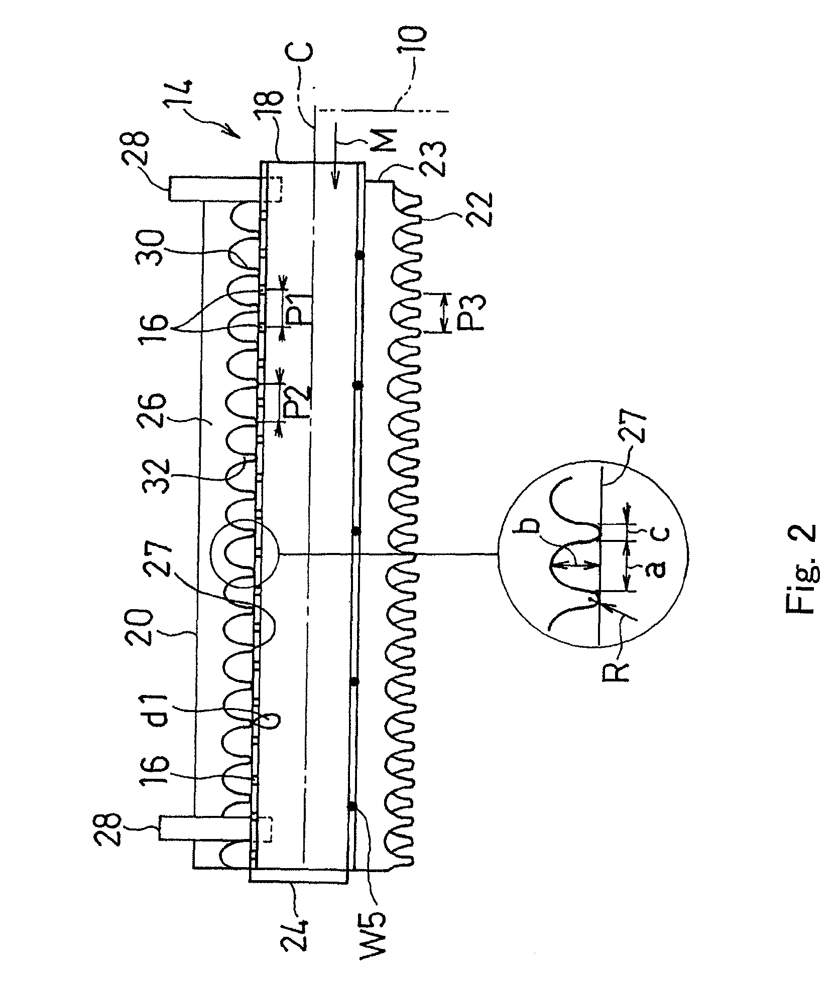
[0029]Hereinafter, preferred embodiments of the present invention will be explained in reference to the drawings. FIG. 1 shows an evaporator 2 that is one type of heat exchanger according to Embodiment 1 of the present invention. The evaporator 2 is used for a binary turbine configured to use as a heat source 4 hot water generated in an iron mill, a ceramic industry, or the like and use a low boiling point material as a working medium M. Hot water H is supplied from the heat source 4 through a pipe 5 to the evaporator 2. The working medium M is vaporized by heat exchange with the hot water H flowing through heat-transfer tubes 6 in the evaporator 2, that is, heat exchange with the heat source 4. The gas-phase working medium M is supplied through a gas-phase medium supply passage 8 to the binary turbine of a power generating unit, not shown. The gas-phase working medium M discharged from the binary turbine flows through a condenser, not shown, to become a liquid phase. Then, the liqu...


PUM


Abstract

Disclosed is a spraying tube device capable of, even in a case where a spray solution having low latent heat is used in a falling film type evaporator, uniformly spraying the spray solution to a heat-transfer tube, and a heat exchanger using the spraying tube device. The spraying tube device includes: a spraying tube configured to eject a spray solution M upward through ejection holes arranged along a tube axis C; a cover arranged above the spraying tube and configured to receive the ejected spray solution M and cause the spray solution M to flow through a space S between the cover and the spraying tube to flow downward on an outer surface of the spraying tube, and fins configured to uniformize in a tube axis C direction a distribution of the spray solution M having flowed downward from the cover.

Description

TECHNICAL FIELD[0001]The present invention relates to a spraying tube device used in a heat exchanger, such as a falling film type evaporator, and a heat exchanger using the spraying tube device.BACKGROUND ART[0002]The boiling point of a working medium of a binary turbine using low-temperature exhaust heat as a heat source needs to be a low temperature. Therefore, used as the working medium is not water but freon, alternative freon, or the like having a low boiling point. However, since such a low boiling point gas is expensive, there is a demand to reduce a holding gas amount as much as possible. Here, it is thought that a falling film type evaporator used in an absorption refrigerating machine and having a high heat-exchange efficiency is adopted as the evaporator of the binary turbine (for example, PTL 1).CITATION LISTPatent Literature[0003]PTL 1: Japanese Laid-Open Patent Application Publication No. 51-51040[0004]FIGS. 9 and 10 each shows a spraying tube device of the evaporator...

Claims


Application Information

Patent Timeline
Patent Type & Authority Patents(United States)
IPC IPC(8): F28D3/04F25B39/02F28D3/02B05B1/26B05B7/00
CPCB05B1/265F25B39/028F28D3/02F28D3/04B05B7/0012
Inventor OKUMURA, TAKESHIMIYAKE, NAOKITAKEMURA, TADASHI
Owner KAWASAKI HEAVY IND LTD
Why Eureka
Try Eureka