
Cabinet hardware with braking and shock absorbing device

a technology of shock absorption device and cabinet hardware, which is applied in the direction of hinges, manufacturing tools, wing accessories, etc., can solve the problems of reducing the size of the pump, the damper has a high static friction, and the kinetic energy of the movable cabinet parts cannot be reduced in the amount necessary, so as to achieve the effect of being cheap to produ

Inactive Publication Date: 2005-03-01
GRASS GMBH
View PDF23 Cites 34 Cited by
  • Summary
  • Abstract
  • Description
  • Claims
  • Application Information

AI Technical Summary

Benefits of technology

Furthermore, vibrations or impact noises are prevented during the closing process; that is, the movable cabinet component that can have varying mass and speed, should brake almost free from wear and tear over a certain distance (e.g. the closing angle).
Furthermore, depending on the type of movement transfer between the driver plate and brake plate, a considerably larger “braking distance” can be attained in comparison to the linear movement distance, which is defined by the rotation angle of the brake plate. Further, the relative velocity of the brake plate is greater in comparison to the speed of the driver plate, which, likewise, affects the attainable braking action positively.
The use of two or more brake plates can increase the obtainable braking force substantially. Moving in opposite directions can double the speed of the brake plates relative to one another and can, thereby, also double the relative “braking distance.”
Compared with known braking and damping devices of cabinet fittings, the invention offers substantial advantages.
A further advantage is the suggested braking and damping elements are quite inexpensive to produce and can be integrated into the cabinet fitting.

Problems solved by technology

Such buffers are very well suited for moderating noise, but are, however, not suitable for diminishing the kinetic energy of the movable cabinet parts in the amount necessary.
Such dampers have a high static friction, due to the piston rod and piston sealing, which sets a reduction of the borders of the pump size.
Furthermore, they are complex and expensive and are not suitable, therefore, as integrated dampers in cabinet fittings.
Likewise, the wear and tear plays a large role with friction damping, especially if masses with high kinetic energy must be braked.

Method used


Image

  • Cabinet hardware with braking and shock absorbing device
  • Cabinet hardware with braking and shock absorbing device
  • Cabinet hardware with braking and shock absorbing device

Examples


Embodiment Construction

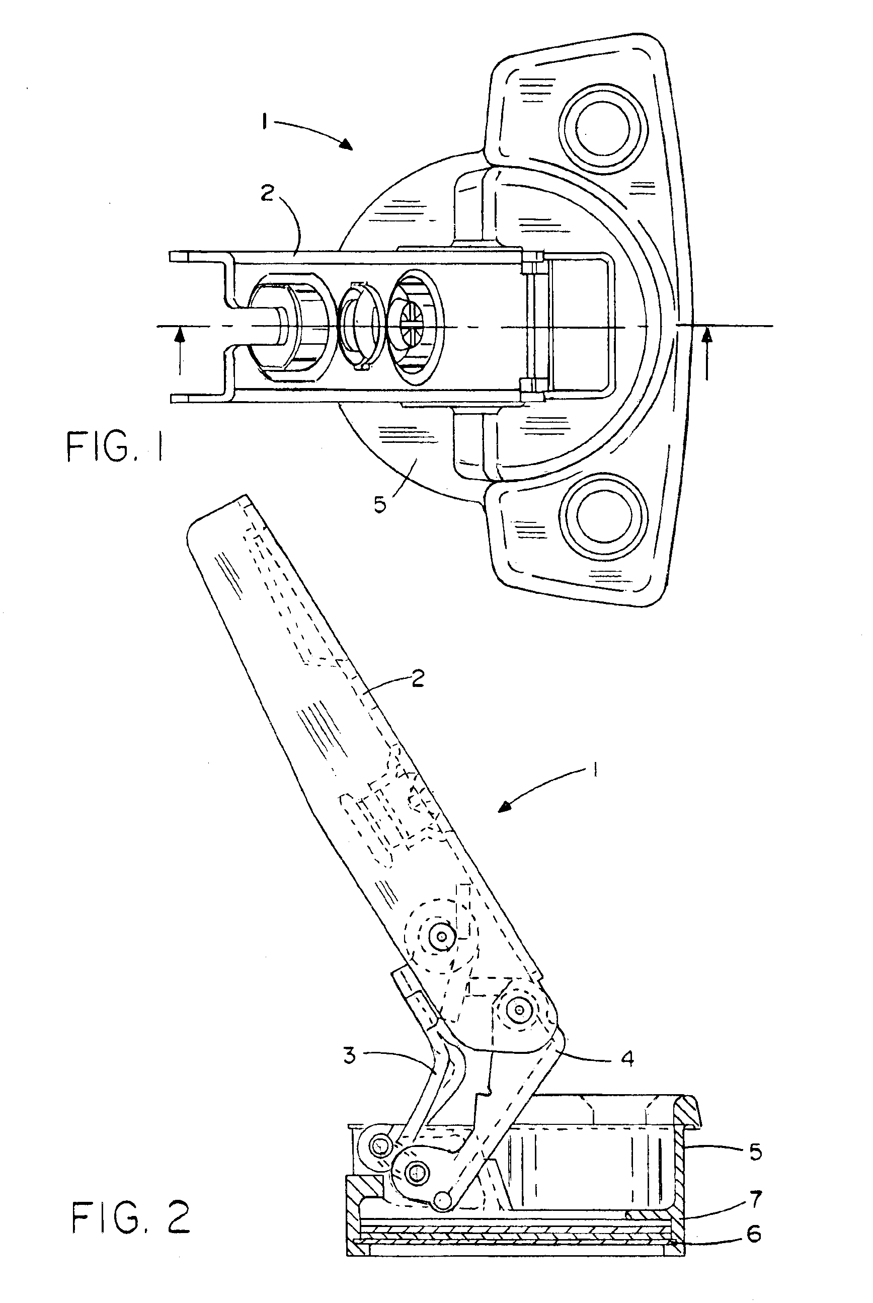
FIGS. 1 and 2 show a cabinet hinge (1), by means of which a cabinet component (for example, a cabinet door), can be fastened movable to a cabinet body. The cabinet door can be opened, thereby, within the range of an opening angle, so that closes, within the range of a closing angle, automatically by the cabinet hinge (1). This automatic closing movement applies to the braking and damping, since the cabinet door would, otherwise, impact hard on the cabinet body.

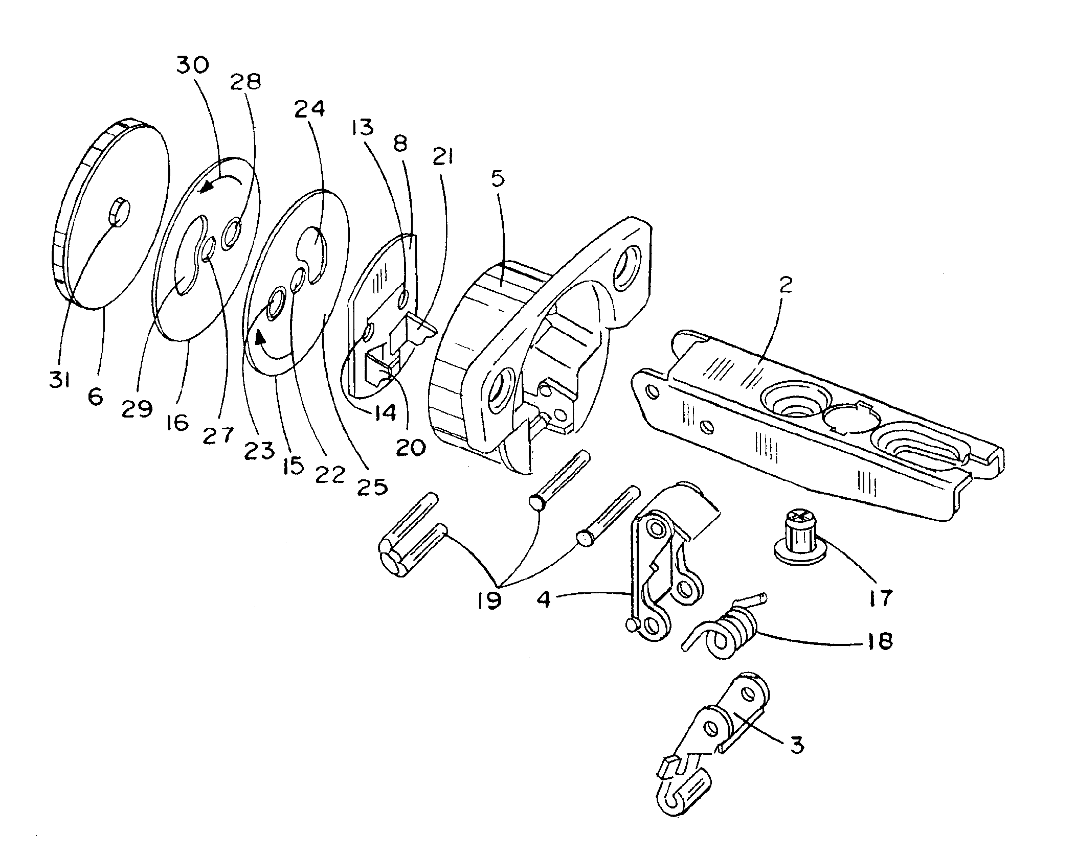
The cabinet hinge (1) includes a hinge arm (2) that is fastened to the cabinet door and that is connected swiveling by an outer and an inner articulated lever (3, 4) with a hinge cup (5). The hinge cup is locked by a base plate (6) and contains the invention-related braking and damping device (7), which produces the necessary braking action when the cabinet hinge is closed.

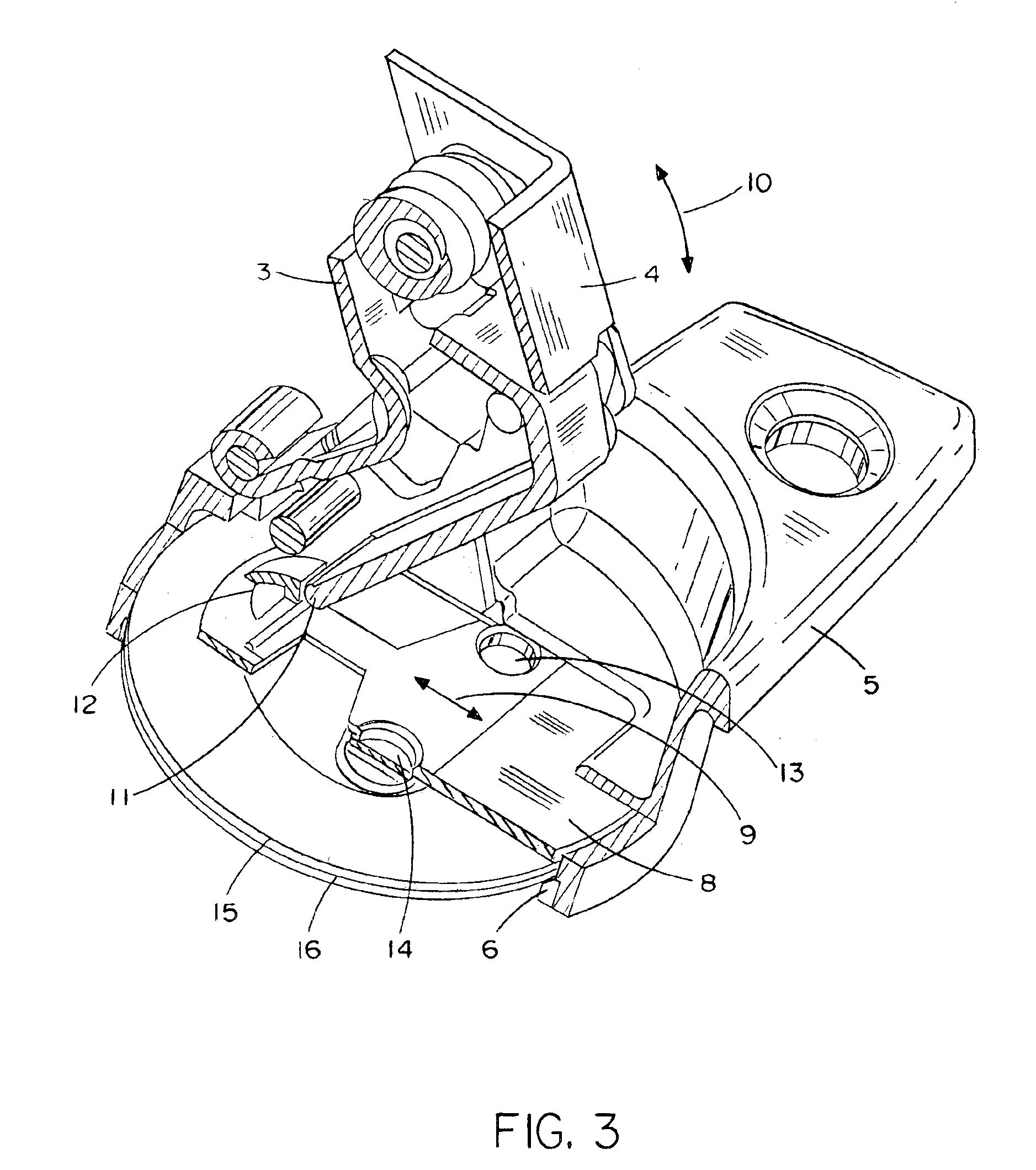
As shown in FIG. 3, there is a driver plate (8) in the cup base area, which is held linearly movable in arrow direction (9). The moving or shifting results ...


PUM


Abstract

The invention concerns a cabinet fitting, in particular a hinge, with integrated braking and damping device, including a fastenable hinge arm on a cabinet component and a fastenable hinge cup on another movable cabinet component that is connected by at least one articulated lever with the hinge arm. The invention is characterized by the driver plate, which can slide, is held in the hinge cup and can be operated directly or indirectly by the articulated lever and has held in the hinge cup at least one pivoting or swiveling brake plate moves turning, so that the brake plate has at least one brake surface that glides on at least one corresponding, fixed brake surface or, on one opposite the first brake surface, a second movable brake surface.

Description

FIELD OF THE INVENTIONThe invention concerns a cabinet fitting, in particular a cabinet hinge, with a braking and damping device.BACKGROUND OF THE INVENTIONDamping and braking devices are well known in different variations in the present technology and are used in assorted areas of application. There are currently damping elements for movable cabinet parts in the form of simple buffers on the market. Such buffers are very well suited for moderating noise, but are, however, not suitable for diminishing the kinetic energy of the movable cabinet parts in the amount necessary. Another further development of a ductile buffer that is integrated in a hinge is described in DE-OS 27 08 545. Here, a flexible damping element is located between the hinge links of a cabinet hinge and deforms shortly before reaching the hinge's open position. A similar damping element for cabinet hinges is shown by AT-PS 349 931. Here, there is a flexible attenuator between the hinge arm and hinge cup on which th...

Claims


Application Information

Patent Timeline
IPC IPC(8): E05D5/08E05D11/00E05D11/10E05F5/02E05F5/00E05D5/00E05F1/00E05F3/16E05F1/12E05F3/00E05D11/08
CPCE05D11/087E05F5/006E05D11/1021E05Y2201/21E05Y2201/254E05Y2201/266Y10T16/5324E05Y2600/46E05Y2900/20Y10T16/54025Y10T16/5383Y10T16/5403Y10T16/54029E05Y2201/71E05Y2800/268E05Y2800/73
Inventor EGGER, REMOMUELLER, WOLFGANG
Owner GRASS GMBH
Learn More