Method of manufacturing directional backlight apparatus and directional structured optical film

Inactive Publication Date: 2014-02-13
REALD SPARK LLC
View PDF6 Cites 33 Cited by
  • Summary
  • Abstract
  • Description
  • Claims
  • Application Information

AI Technical Summary

Benefits of technology

[0007]The present embodiments advantageously achieve a convenient and low cost method for manufacturing a stepped waveguide apparatus. At least two different optical functions can be arranged on a single structured optical film and combined with a separate substrate to achieve a stepped imaging directional backlight. Optical functions may include light extraction surfaces, imaging reflectors and lenses, light input coupling optical elements and elements arranged to direct light at the non-guiding sides of the waveguide. Further, many devices can be made in parallel in a roll-to-roll processing manner, thus achieving highly parallel manufacture of large area and large number of devices. Advantageously such structured optical films can be fabricated with low scatter and high efficiency. F

Problems solved by technology

Gaps between the pixels, for example for electrodes, typically produce non-uniform viewing windows.
Undesirably such displays exhibit image flicker as an observer moves laterally with respect to the display and so limi

Method used


Image

  • Method of manufacturing directional backlight apparatus and directional structured optical film
  • Method of manufacturing directional backlight apparatus and directional structured optical film
  • Method of manufacturing directional backlight apparatus and directional structured optical film

Examples


Example

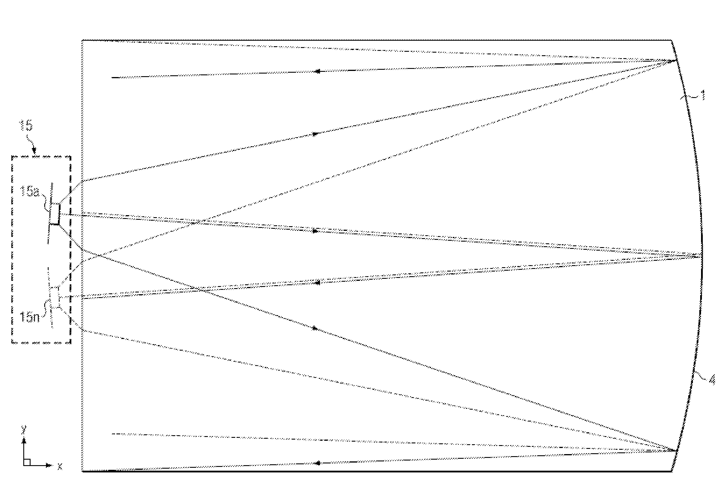
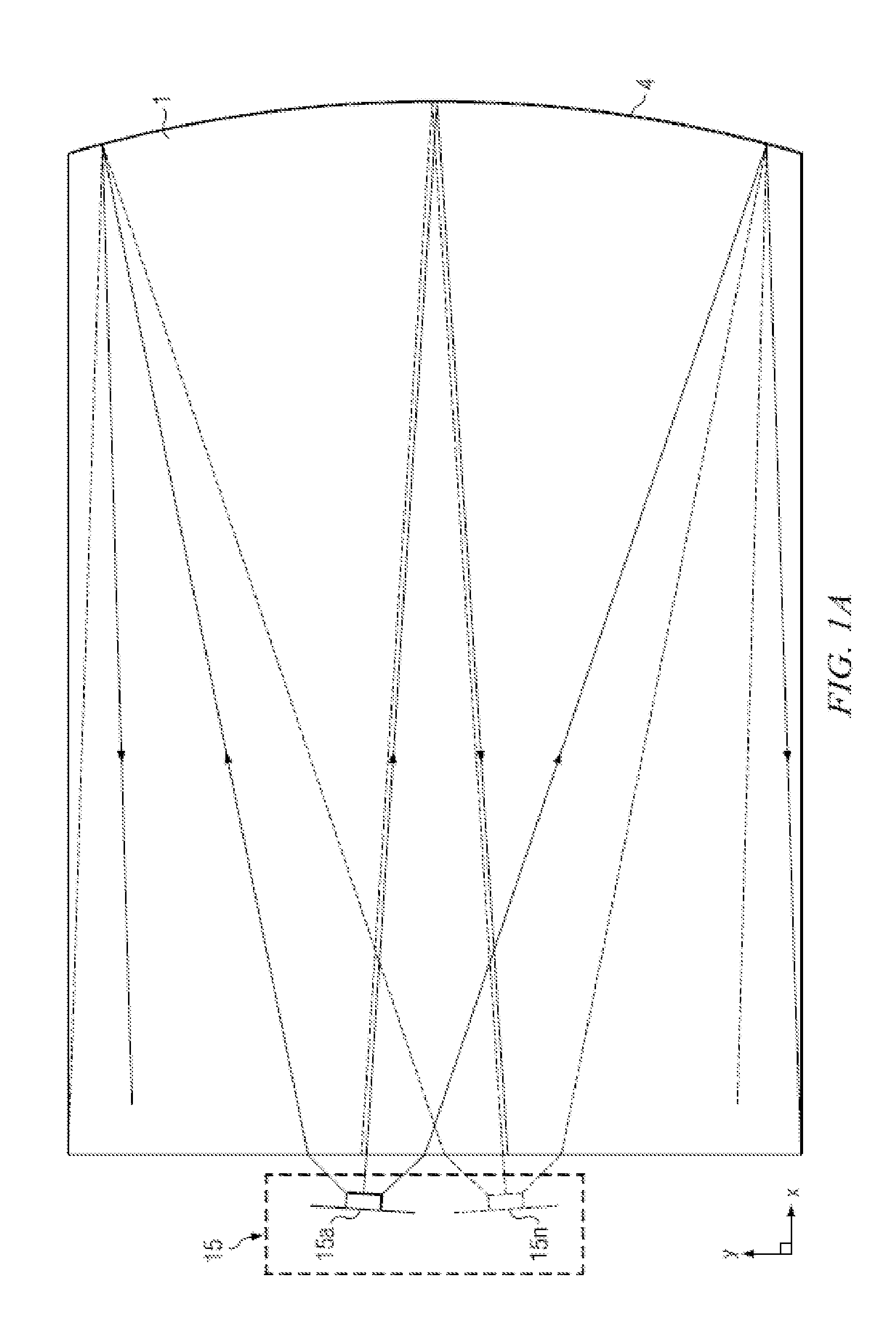
[0070]Time multiplexed autostereoscopic displays can advantageously improve the spatial resolution of autostereoscopic display by directing light from all of the pixels of a spatial light modulator to a first viewing window in a first time slot, and all of the pixels to a second viewing window in a second time slot. Thus an observer with eyes arranged to receive light in first and second viewing windows will see a full resolution image across the whole of the display over multiple time slots. Time multiplexed displays can advantageously achieve directional illumination by directing an illuminator array through a substantially transparent time multiplexed spatial light modulator using directional optical elements, wherein the directional optical elements substantially form an image of the illuminator array in the window plane.

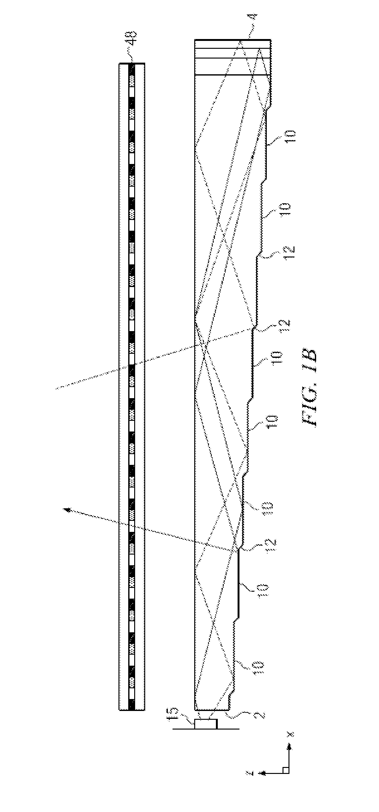
[0071]The uniformity of the viewing windows may be advantageously independent of the arrangement of pixels in the spatial light modulator. Advantageously, such ...


PUM

PropertyMeasurementUnit
Surfaceaaaaaaaaaa
Lightaaaaaaaaaa
Optical propertiesaaaaaaaaaa

Abstract

Disclosed is a manufacturing method for a stepped imaging directional backlight apparatus which may include a structured optical film and a tapered body. The structured optical film may include multiple optical functions and may be assembled by folding onto the tapered body, reducing cost and complexity of manufacture.

Description

CROSS-REFERENCE TO RELATED APPLICATIONS[0001]This application is a continuation-in-part of U.S. patent application Ser. No. 13 / 300,293, entitled “Directional flat illuminators,” filed Nov. 18, 2011, which claims priority to U.S. Provisional Patent Application No. 61 / 415,810, entitled “Directional flat illuminators,” filed Nov. 19, 2010, the entireties of which are herein incorporated by reference. This application also claims priority to U.S. Provisional Application No. 61 / 649,133, entitled “Method of manufacturing directional backlight apparatus and directional structured optical film,” filed May 18, 2012, the entirety of which is herein incorporated by reference.TECHNICAL FIELD[0002]This disclosure generally relates to manufacturing methods for apparatus for illumination of light modulation devices, and more specifically relates to light guides for providing large area illumination from localized light sources for use in 2D, 3D, and / or autostereoscopic display devices.BACKGROUND[0...

Claims


Application Information

Patent Timeline
IPC IPC(8): F21V8/00G02B30/33
CPCG02B6/0065Y10T29/49002G02B6/0055G02B6/0068G02B6/0048G02B30/33G02B30/27G02B6/0025G02B6/0026G02B6/0053G02B6/0061
Inventor ROBINSON, MICHAEL G.WOODGATE, GRAHAM J.HARROLD, JONATHANSHARP, GARY D.SCHUCK, MILLER H.
Owner REALD SPARK LLC
Why Eureka
Try Eureka