

Optical member, optical device and coating liquid
- Summary
- Abstract
- Description
- Claims
- Application Information
AI Technical Summary
Benefits of technology
Problems solved by technology
Method used
Image

Examples
example 1
[0092]While 1-ethoxy-2-propanol (hereafter abbreviated as 1E2P) was added to 580 g of a dispersion of a hollow silicon oxide particle in isopropyl alcohol (manufactured by JGC Catalysts and Chemicals Ltd., THRULYA 1110, average particle diameter: around 50 nm, shell thickness: around 10 nm, solid concentration: 20.5% by mass), isopropyl alcohol was heated and distilled off. Isopropyl alcohol was distilled off until the solid concentration was 19.5% by mass, and 610 g of a liquid of the hollow silicon oxide particle wherein the solvent was replaced with 1E2P (hereafter called a solvent replacement liquid 1) was prepared. A fluorine-containing organic acid (manufactured by Tokyo Chemical Industry Co., Ltd., pentafluoropropionic acid, fluorine number: 5) was added to the obtained solvent replacement liquid 1 so that the component ratio of the hollow silicon oxide particle to the fluorine-containing organic acid was 100 / 1, and a dispersion 1 was obtained.
[0093]To a different container w...
example 2
[0096]A fluorine-containing organic acid (manufactured by Tokyo Chemical Industry Co., Ltd., heptafluorobutyric acid, fluorine number: 7) was added to the solvent replacement liquid 1 so that the component ratio of the hollow silicon oxide particle to the fluorine-containing organic acid was 100 / 1, and a dispersion 2 was obtained.
[0097]The dispersion 2 was diluted with ethyl lactate so that the solid concentration was 4.5% by mass, and the silica sol 1 was then added so that the component ratio of the hollow silicon oxide particle to the silica sol was 100 / 12. The mixture was further mixed and stirred at room temperature for 2 hours to obtain a coating liquid 2 containing the hollow silicon oxide particle.
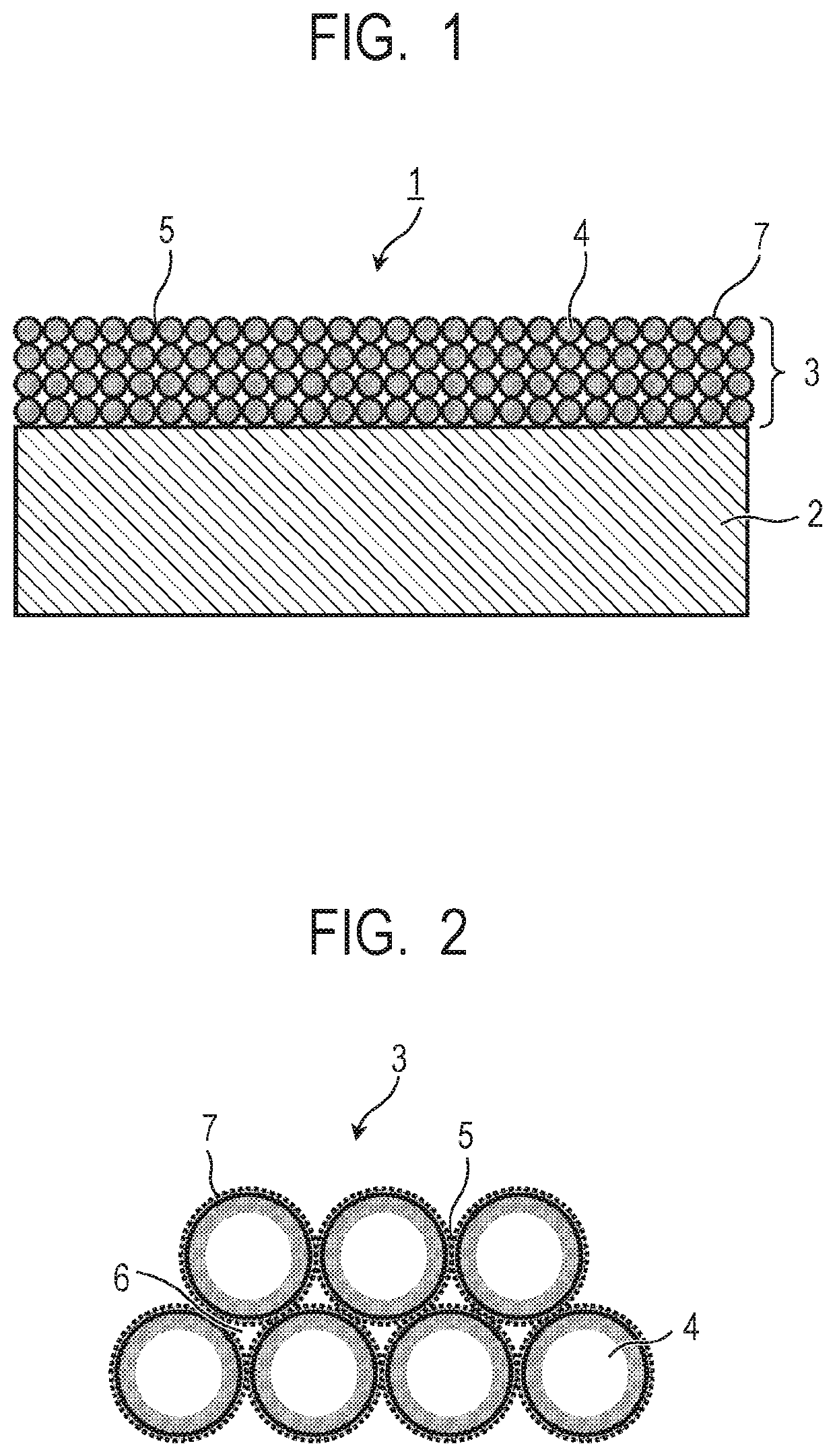
[0098]The obtained coating liquid 2 was dropped on a glass substrate, a film was formed with a spin coater so that the thickness was around 120 nm, firing was then performed in a thermostatic oven at 140° C. for 30 minutes to obtain an optical member 2 having a porous layer 2. The ...
example 3
[0099]A fluorine-containing organic acid (manufactured by Tokyo Chemical Industry Co., Ltd., nonafluorovaleric acid, fluorine number: 9) was added to the solvent replacement liquid 1 so that the component ratio of the hollow silicon oxide particle to the fluorine-containing organic acid was 100 / 1, and a dispersion 3 was obtained.
[0100]The dispersion 3 was diluted with ethyl lactate so that the solid concentration was 4.5% by mass, and the silica sol 1 was then added so that the component ratio of the hollow silicon oxide particle to the silica sol was 100 / 12. The mixture was further mixed and stirred at room temperature for 2 hours to obtain a coating liquid 3 containing the hollow silicon oxide particle.
[0101]The obtained coating liquid 3 was dropped on a glass substrate, a film was formed with a spin coater so that the thickness was around 120 nm, firing was then performed in a thermostatic oven at 140° C. for 30 minutes to obtain an optical member 3 having a porous layer 3. The c...
PUM
| Property | Measurement | Unit |
|---|---|---|
| Molecular weight | aaaaa | aaaaa |
| Strength | aaaaa | aaaaa |
| Acid dissociation constant | aaaaa | aaaaa |
Abstract
Description
Claims
Application Information