Inkjet printer

Active Publication Date: 2016-10-06
RISO KAGAKU CORP
View PDF14 Cites 11 Cited by
  • Summary
  • Abstract
  • Description
  • Claims
  • Application Information

AI Technical Summary

Benefits of technology

[0021]According to the configuration described above, the non-ejection drive ratio is adjusted for the inkjet head at the position coinciding with the end portion of the pr

Problems solved by technology

The temperature increase by the heat generation of the inkjet heads may cause failure of the inkjet heads and the like.
In the case of such an inkjet printer configured to cool a plurality of inkjet heads with cooling air by means of a fan, the inkjet heads are cooled to different degrees depending on their positions, and some inkjet head may

Method used


Image

  • Inkjet printer
  • Inkjet printer
  • Inkjet printer

Examples


first embodiment

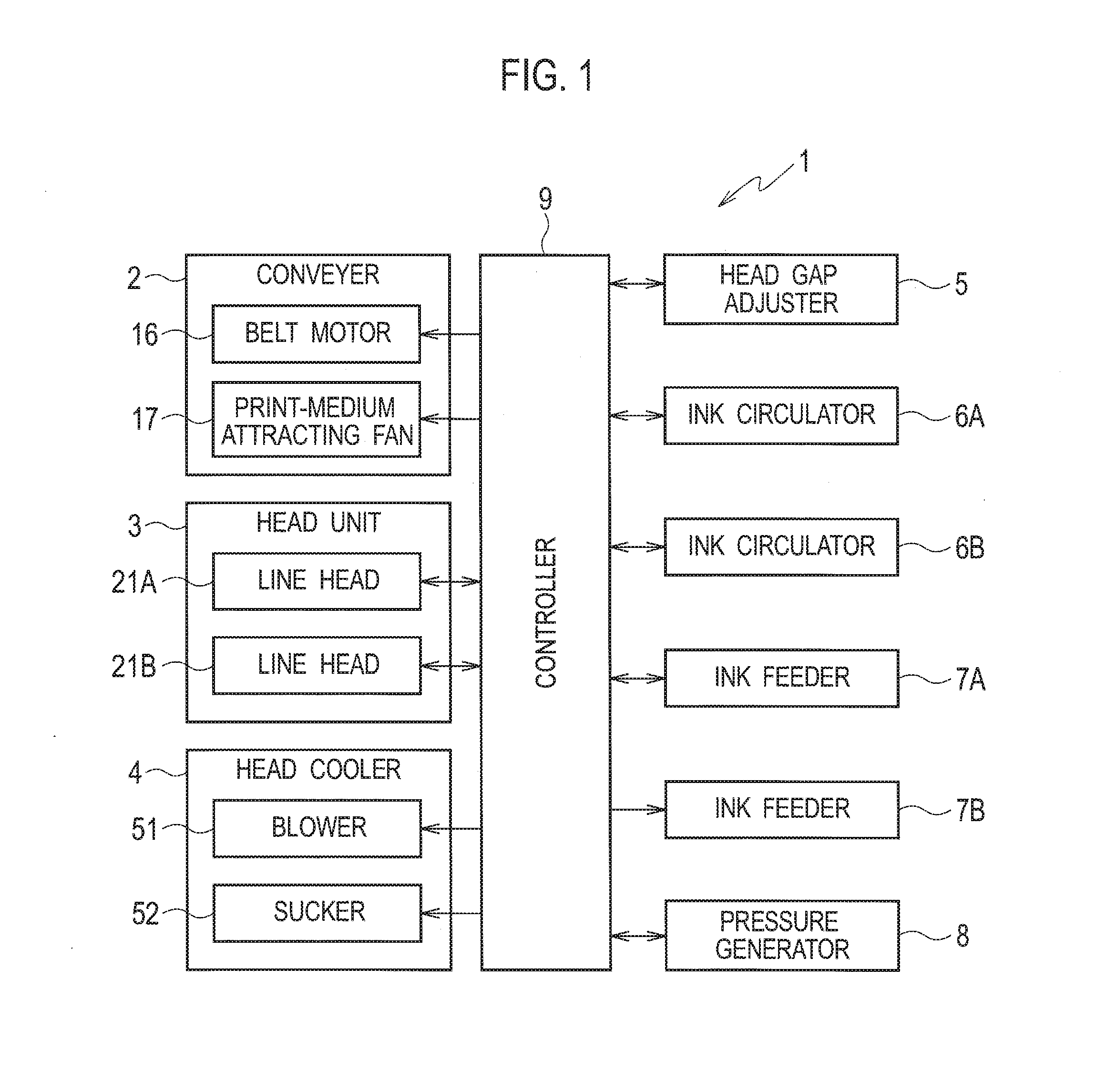
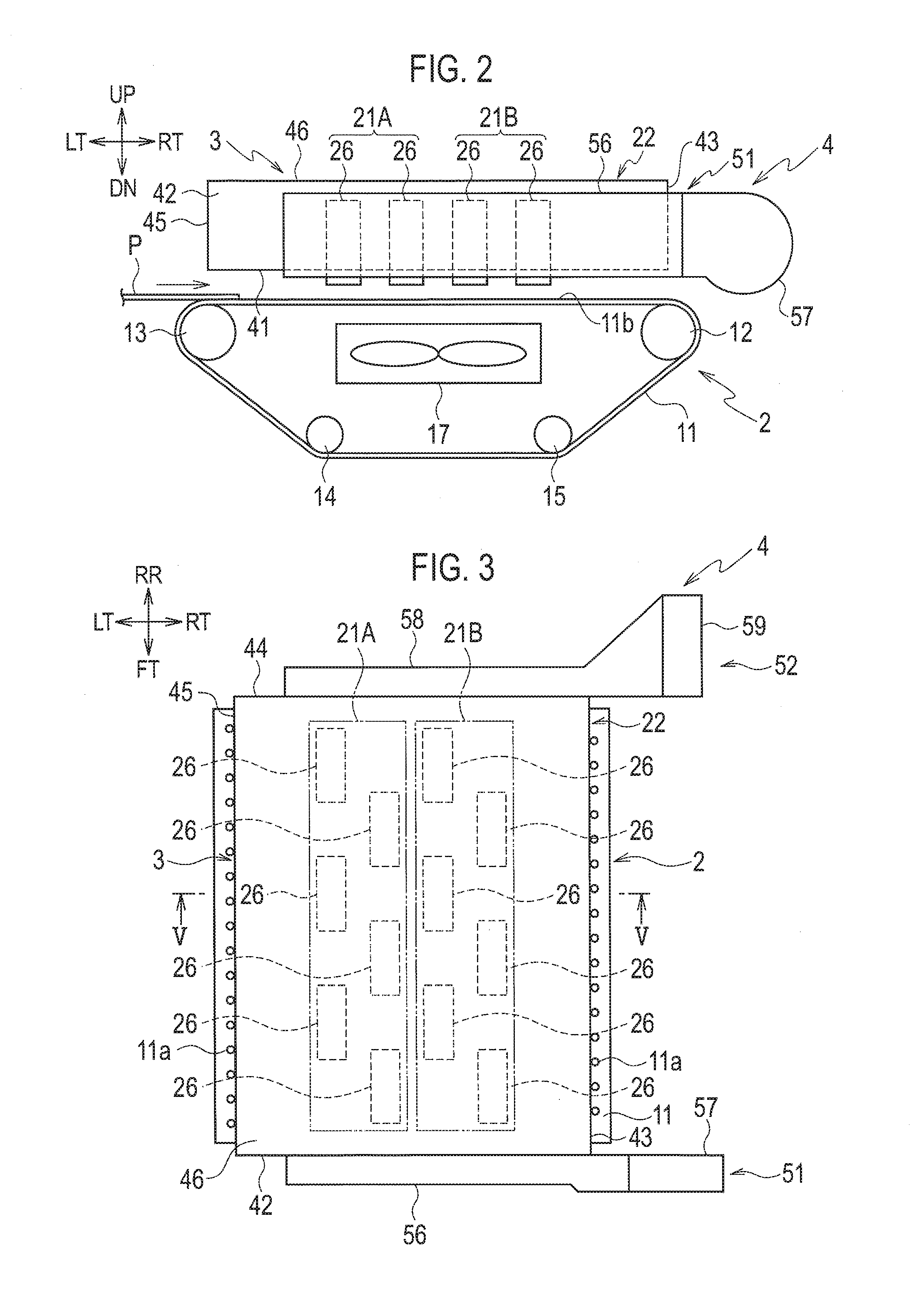
[0052]FIG. 1 is a block diagram illustrating the configuration of an inkjet printer 1 according to a first embodiment. FIG. 2 is a schematic configuration diagram of a conveyer 2, a head unit 3, and a head cooler 4 of the inkjet printer 1, which is illustrated in FIG. 1. FIG. 3 is a plan view of the conveyer 2, the head unit 3, and the head cooler 4. FIG. 4 is an exploded perspective view of the head unit 3 and the head cooler 4. FIG. 5 is a partially-enlarged cross-sectional view of the conveyer 2 and the head unit 3 taken along line V-V in FIG. 3. FIG. 6 is a partial cross-sectional view of an inkjet head. 26 taken along a horizontal plane. FIG. 7 is a schematic configuration diagram of an ink circulator 6 (6A, 6B), an ink feeder 7 (7A, 7B), and a pressure generator 8 of the inkjet printer 1, which is illustrated in FIG. 1. FIG. 8 is a block diagram illustrating the configuration of a controller 9 of the inkjet printer 1, which is illustrated in FIG. 1. FIG. 9 is a block diagram i...

second embodiment

[0222]Next, description will be given of a second embodiment which involves a change in the precursor-ratio setting process in the embodiment described above.

[0223]In the second embodiment, an image processor 122 is configured to calculate a print coverage rate Ra for each inkjet head 26 page by page based on image data.

[0224]A CPU 151 of an actuator controller 124 is configured to calculate a precursor ratio Rp by using the print coverage rate Ra in a precursor-ratio setting process. FIG. 21 is a flowchart of the precursor-ratio setting process in the second embodiment.

[0225]In Step S41 in FIG. 21, the CPU 151 reads a positional coefficient Kp of each inkjet head 26 from a ROM 152.

[0226]Then, in Step S42, the CPU 151 reads the print coverage rate Ra of each inkjet head 26 from the image processor 122.

[0227]Then, Step S43, the CPU 151 calculates the precursor ratio Rp. In the second embodiment, the precursor ratio Rp is calculated from Equation (3) below.

Rp(%)=Kp=(100−Ra)   (3)

[0228...

third embodiment

[0232]Next, description will be given of a third embodiment which involves a change in the precursor-ratio setting process in the embodiments described above.

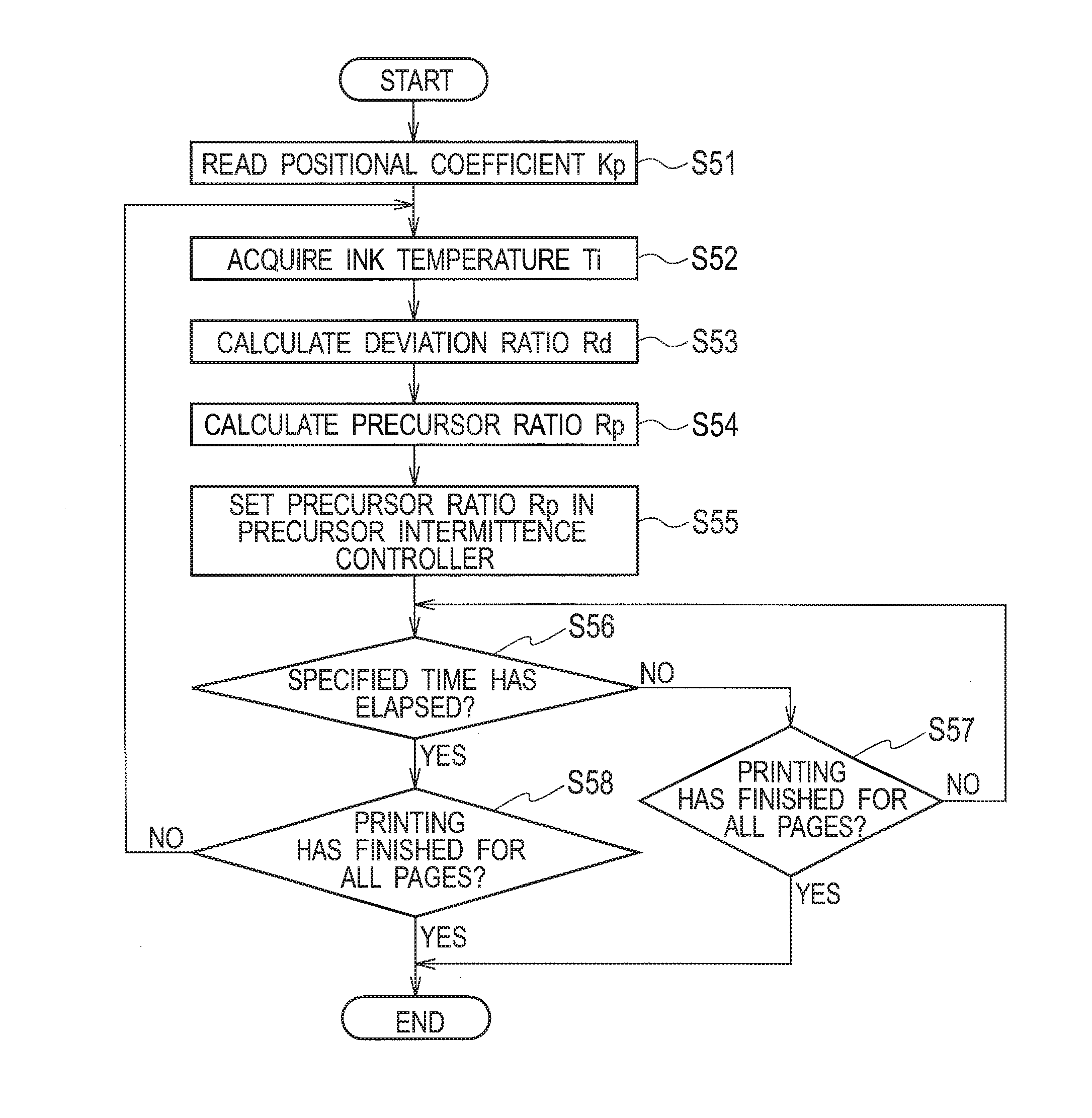
[0233]FIG. 23 is a flowchart of a precursor-ratio setting process in the third embodiment.

[0234]In Step S51 in FIG. 23, a CPU 151 of an actuator controller 124 reads a positional coefficient Kp of each inkjet head 26 from a ROM 152.

[0235]Then, in Step S52, the CPU 151 acquires an ink temperature Ti at the inkjet head 26 from its head-ink temperature sensor 68.

[0236]Then, in Step S53, the CPU 151 calculates a deviation ratio Rd of the ink temperature Ti from a reference temperature Tk. The deviation ratio Rd is calculated from Equation (4) below.

Rd(%)=((Tk−Ti) / Tk)×100   (4)

[0237]Then, in Step S54, the CPU 151 calculates a precursor ratio Rp. In the third embodiment, the precursor ratio Rp is calculated from Equation (5) below.

Rp(%)=Kp×Rd   (5)

[0238]As a result, as illustrated in FIG. 24, the precursor ratio Rp corresponding to t...


PUM


Abstract

An inkjet printer includes a conveyer, a plurality of inkjet heads, a head cooler configured to generate cooling air and cool the plurality of inkjet heads by the generated cooling air, and a controller. The controller is configured to drive the plurality of inkjet heads to perform non-ejection drive on at least one of lines which involve no ink ejection, the non-ejection drive being driving of the plurality of inkjet heads to such a degree as to eject no ink. The controller is configured to determine a non-ejection drive ratio for each of the plurality of inkjet heads in accordance with a position of each of the plurality of inkjet heads, the non-ejection drive ratio being a ratio of lines on which the controller performs the non-ejection drive to the lines which involve no ink ejection.

Description

CROSS REFERENCE TO RELATED APPLICATION[0001]This application is based upon and claims the benefit of priority from the prior Japanese Patent Application No. 2015-072212, filed on Mar. 31, 2015, the entire contents of which are incorporated herein by referenceBACKGROUND[0002]1. Technical Field[0003]The disclosure relates to an inkjet printer configured to perform printing by ejecting an ink from inkjet heads.[0004]2. Related Art[0005]In an inkjet printer, inkjet heads generate heat as a result of ink ejection. The temperature increase by the heat generation of the inkjet heads may cause failure of the inkjet heads and the like. For this reason, it is necessary to cool the inkjet heads to suppress the temperature increase.[0006]To do so, Japanese Unexamined Patent Application Publication No. 2010-264752 proposes a technique of cooling inkjet heads by sending cooling air to the inkjet heads means of fans.SUMMARY[0007]In the case of such an inkjet printer configured to cool a plurality ...

Claims


Application Information

Patent Timeline
IPC IPC(8): B41J29/377B41J2/01
CPCB41J2/01B41J29/377
Inventor NAKAMURA, HIROYUKI
Owner RISO KAGAKU CORP
Why Eureka
Try Eureka