
Air purifier with ozone reduction arrangement

a technology of air purifier and ozone reduction, which is applied in the direction of transportable electrostatic units, electric supply techniques, magnetic separation, etc., can solve the problems of affecting the overall performance of the air purifier, the release of ozone through this ionization process is not controlled by a controlling mechanism, and the harm caused by unregulated ozone generation is further intensified. achieve the effect of optimally controlling the amount of ozone and not affecting the overall performance of the air pur

Inactive Publication Date: 2008-03-06
LIANG ZHUHUAN
View PDF11 Cites 2 Cited by
  • Summary
  • Abstract
  • Description
  • Claims
  • Application Information

AI Technical Summary

Benefits of technology

[0010]A main object of the present invention is to provide an air purifier comprising an ozone reduction module for optimally controlling the amount of ozone generated by the air purifier without affecting the overall performance of the air purifier.
[0013]Another object of the present invention is to provide an air purifier which does not involve complicated mechanical and electrical components so as to minimize the manufacturing cost of the present invention.
[0019]an ozone reduction module electrically connecting to the power unit for generating heat within the air purifying cavity, wherein when a temperature within the air purifying cavity reaches a preset temperature, a level of ozone generated by the ionizing electrode unit is substantially minimized and controlled for preventing excess generation of ozone.

Problems solved by technology

Despite its usefulness and advantages, there is a pressing problem for almost all kinds of conventional air purifiers.
However, for almost all conventional air purifiers, there exists no controlling mechanism for regulating the release of ozone through this ionization process.
This harm caused by unregulated ozone generation is further intensified when these air purifiers are used in a confined area, such as in a bedroom with poor air ventilation.
For this sort of environment, prolonged use of conventional air purifier will certainly affect the health of the user and substantially defeat the very purpose of having such an air purifier, i.e. to maintain sufficiently clean air for maintaining good health for the users of air purifiers.
Although this strategy may actually reduce ozone emission from the ionizing electrodes, this reduces the overall effectiveness of the air purifier in that its ability for collecting dust and killing germs and bacteria will be significantly reduced.

Method used


Image

  • Air purifier with ozone reduction arrangement
  • Air purifier with ozone reduction arrangement
  • Air purifier with ozone reduction arrangement

Examples


Embodiment Construction

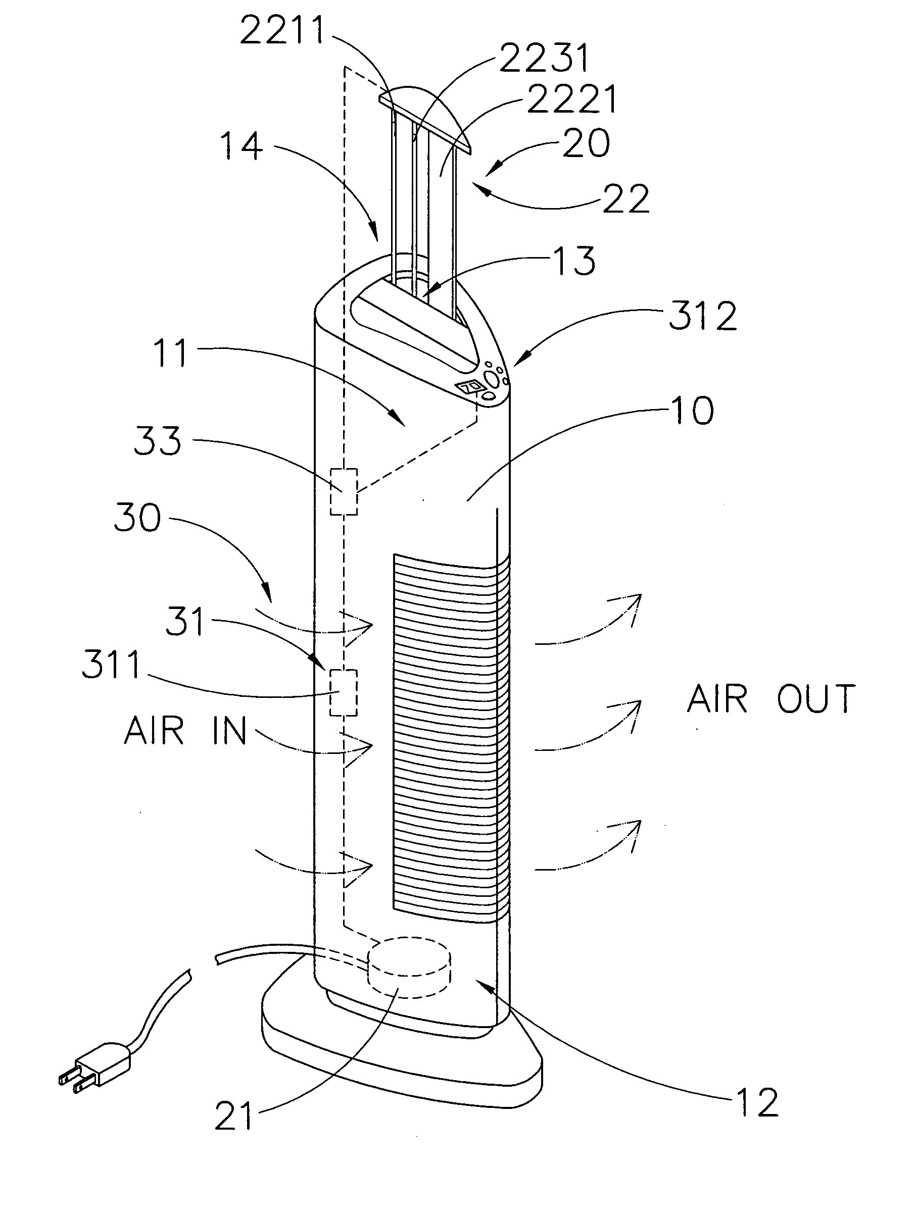
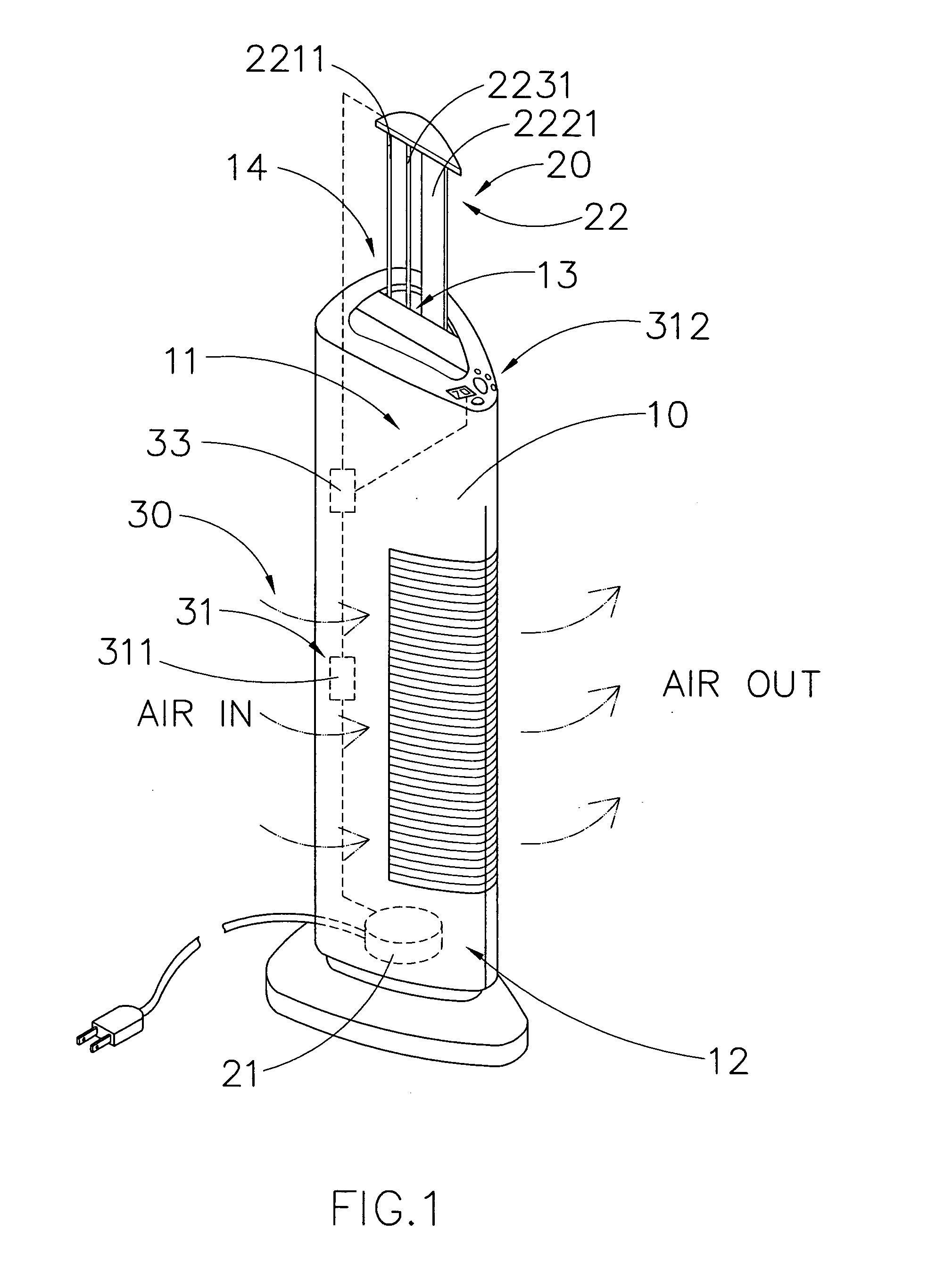
[0026]Referring to FIG. 1 to FIG. 3 of the drawings, an air purifier according to a preferred embodiment of the present invention is illustrated, in which the air purifier comprises an outer case 10, an ionizer module 20, and an ozone reduction module 30.

[0027]The outer case 10 has a top portion 11, a bottom portion 12, an air purifying cavity 13 defining between the top and the bottom portion 11, 12, and a peripheral opening 14 communicating with the air purifying cavity 13.

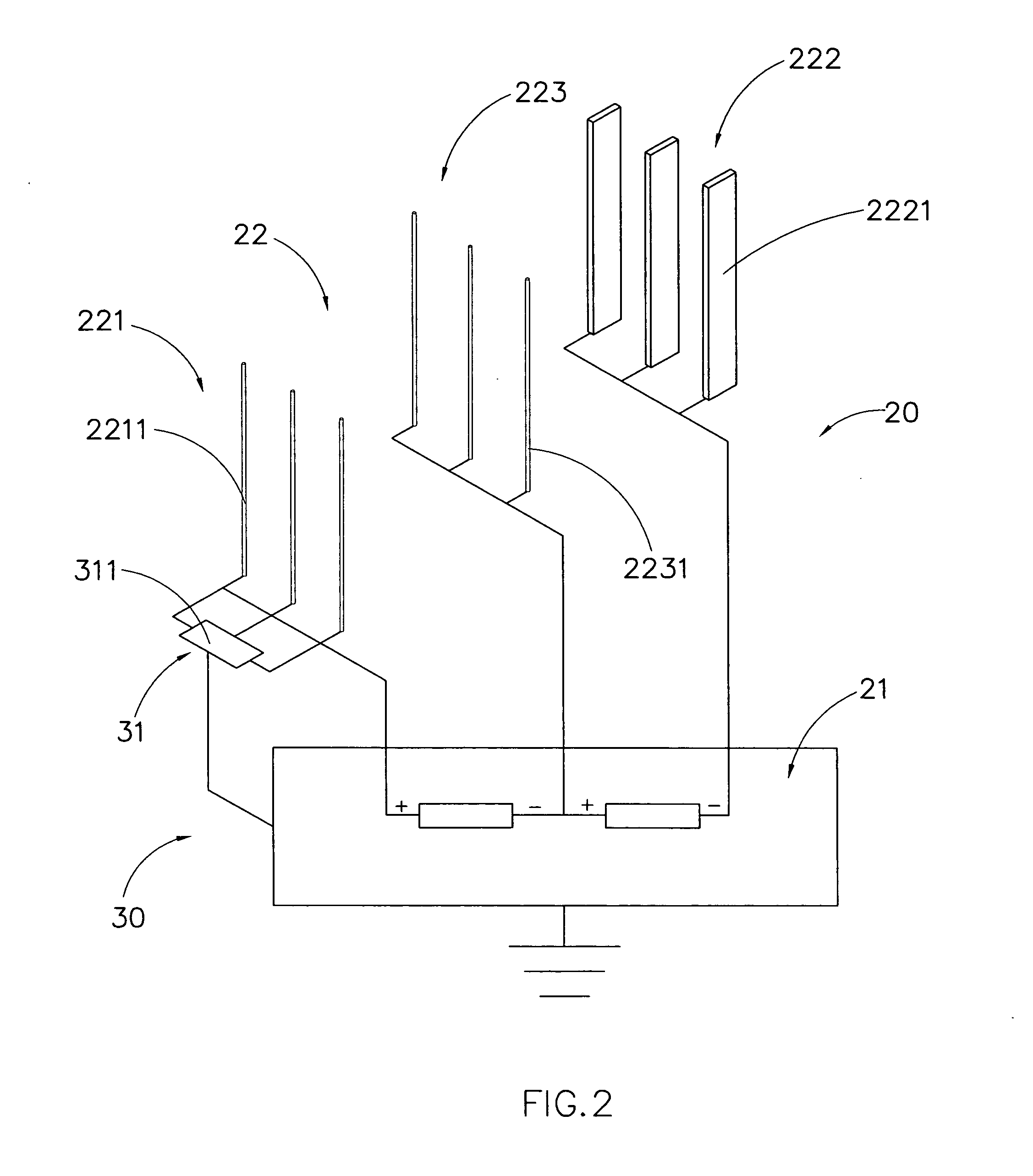
[0028]The ionizer module 20 comprises a power unit 21 and an ionizing electrode unit 22. The power unit 21 is supported at the outer casing 10, wherein the power unit 21 comprises an electrode terminal.

[0029]The ionizing electrode unit 22 is supported within the air purifying cavity 13 to electrically couple with the electrode terminal for ionizing ambient air in a vicinity of the ionizing electrode unit 22 to generate an airflow and ozone within the air purifying cavity 13 to exit at the peripheral opening 14 o...


PUM


Abstract

An air purifier includes an outer case having an air purifying cavity, an ionizer module, and an ozone reduction module. The ionizer module includes a power unit and an ionizing electrode. The ozone reduction module is electrically connected to the power unit for generating heat within the air purifying cavity, wherein when a temperature within the air purifying cavity reaches a preset temperature, a level of ozone generated by the ionizing electrode unit is substantially minimized and controlled for preventing excess generation of ozone.

Description

BACKGROUND OF THE PRESENT INVENTION[0001]1. Field of Invention[0002]The present invention relates to an air purifier, and more particularly to an air purifier comprising an ozone reduction module for optimally controlling the amount of ozone generated by the air purifier.[0003]2. Description of Related Arts[0004]Air purifiers have widely been utilized all over the world for providing extra ozone emission to ambient air in indoors environment. For example, one may put an air purifier in his / her living room for enhancing the air quality therewithin.[0005]A conventional air purifier typically comprises an outer casing and an ionizer module supported in the outer casing for ionizing ambient air and releasing a predetermined level of ozone to the ambient air in which the air purifier is operating. The ionizer module usually comprises a plurality of ionizing electrodes electrically connected to a power supply for conducting electricity so as to generate electricity field for ionizing the ...

Claims


Application Information

Patent Timeline
Patent Type & Authority Applications(United States)
IPC IPC(8): B03C3/019
CPCB03C3/019B03C3/32B03C2201/28B03C2201/10B03C2201/06
Inventor LIANG, ZHUHUAN
Owner LIANG ZHUHUAN
Learn More