Energy management system

a technology of energy management and energy management, applied in the direction of transportation and packaging, arrangement of several simultaneous batteries, dc source parallel operation, etc., can solve the problems of high cost and require an advanced controller, and achieve the effect of less complex

Active Publication Date: 2014-05-22
NILAR INT AB
View PDF8 Cites 0 Cited by
  • Summary
  • Abstract
  • Description
  • Claims
  • Application Information

AI Technical Summary

Benefits of technology

[0007]An object with the present invention is to provide a system for supplying power to a network

Problems solved by technology

However, although the system disclosed in U.S. Pat. No. 7,248,490 relates to a power grid application in which individual battery s

Method used


Image

  • Energy management system
  • Energy management system
  • Energy management system

Examples


first embodiment

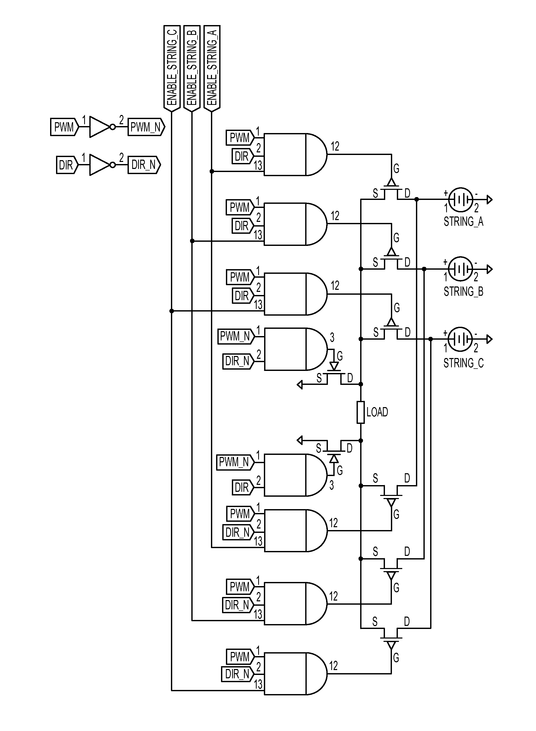
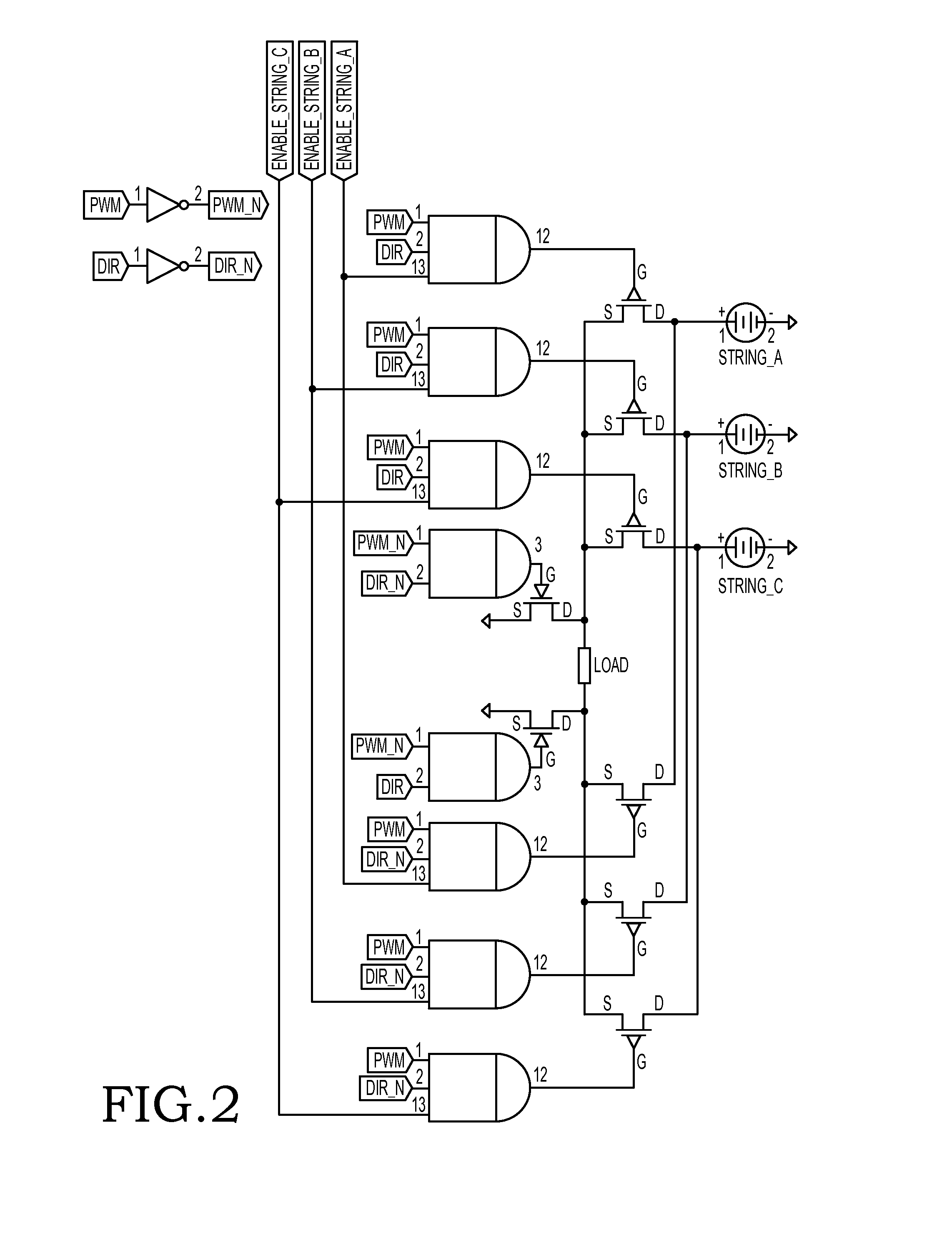
[0026]FIG. 2 shows an energy management system with an energy storage that is divided into several battery strings, in this embodiment only three battery strings STRING_A, STRING_B and STRING_C are illustrated but it is naturally possible to have an arbitrary number of battery strings such as fifteen or more. Each battery string, e.g. STRING_A, is in this example connected to two power switches, each being connected to the opposite upper leg of an H-bridge converter. The power switches are controlled by control signals via AND-gates with three inputs. The control signals are similar compared to the prior art system disclosed in FIG. 1, but the ENABLE signal is replaced by separate enable signals for each string, e.g. ENABLE_STRING_A. Individual battery string control units (not shown) are arranged to monitor each battery string and to generate the enable signal for the respective string when appropriate (as discussed above).

[0027]The major advantage with the embodiment is that it is...

second embodiment

[0030]FIG. 3 shows an energy management system with integrated energy storage and a first type of DC / DC converter. The DC / DC converter is a buck converter, which has a fairly simple operation with an inductor, a diode, a capacitor and a switch. In this embodiment, the switch is realised as three parallel-connected power switches, each being connected to a battery string (or battery) and is controlled by two control signals through an AND-gate. An enable-signal controls which strings are connected to the buck converter, as illustrated by “String 1 Enable”, “String 2 Enable” and “String 3 Enable”, and the control signal PWM determines the DC voltage over the load.

[0031]Individual battery string control units (not shown) monitors the status of each battery string and generates the enable signal if the battery string is determined to be connected to the buck converter and thus the DC load.

third embodiment

[0032]FIG. 4 shows an energy management system with integrated energy storage and a second type of DC / DC converter. The DC / DC converter is an inverting power converter, which has a fairly simple operation with an inductor, a diode, a capacitor and a switch. In this embodiment, the switch is realised as three parallel-connected power switches, each being connected to a battery string (or battery) and is controlled by two control signals through an AND-gate. An enable-signal controls which strings are connected to the inverting power converter, as illustrated by “String 1 Enable”, “String 2 Enable” and “String 3 Enable”, and the control signal PWM determines the DC voltage over the load.

[0033]As mentioned above, individual battery string control units (not shown) monitors the status of each battery string and generates the enable signal if the battery string is determined to be connected to the inverting power converter and thus the DC load.


PUM


Abstract

The present invention relates to an energy management system comprising an energy storage, a control system and a power converter supplying power to a load. The energy storage is arranged in individual energy units and the power converter is provided with a switching system for controlling the voltage over the load. The switching system comprises multiple parallel-connected power switches and at least one of the power switches is connected to each energy unit. The control system comprises individual control units, each being configured to monitor the status of a dedicated energy unit and produce an individual enable signal indicative of the status. Each power switch is configured to be controlled by the individual enable signal and a first control signal, wherein the control system is configured to connect multiple energy units in parallel to the load.

Description

TECHNICAL FIELD[0001]The present invention relates to an energy management system, especially adapted for high power applications, as defined in claim 1.BACKGROUND[0002]An energy storage, e.g. used in electric vehicles, smart grids and active UPS (Uninterruptable Power Supply), normally requires a battery pack with parallel-connected battery strings to obtain suitable power ratings. For instance, if a battery string has a nominal voltage of 180 V and provides 20 Ah, thus having a power rating of 3.6 kWh, fifteen parallel-connected battery strings need to be provided to obtain an energy storage of 54 kWh.[0003]Traditionally the battery pack (with the parallel-connected battery strings) is connected to a power converter circuit that converts the DC power stored in the batteries to AC power to a load. The power converter circuit may be implemented as an H-bridge, wherein the upper legs of the H-bridge each comprises several parallel-connected power switches connected to the battery pac...

Claims


Application Information

Patent Timeline
IPC IPC(8): H02J1/10
CPCH02J1/102H02J7/0014H02J7/34H02M3/1584Y02T10/70H02J7/0048H02J7/0019
Inventor HOWLETT, RICHARD
Owner NILAR INT AB
Why Eureka
Try Eureka