
Electrical generator assembly

a technology of electric generators and enclosures, applied in the direction of machines/engines, mechanical energy handling, mechanical equipment, etc., can solve the problems of limiting the degree to which some enclosures can be opened, damage to the generator, and difficulty in servicing many components

Active Publication Date: 2016-10-06
CHAMPION POWER EQUIP
View PDF4 Cites 18 Cited by
  • Summary
  • Abstract
  • Description
  • Claims
  • Application Information

AI Technical Summary

Benefits of technology

The invention relates to standby generators and multi-chamber generators. The enclosure for standby generators includes a frame, sidewalls, and doors that pivot about the top edge of the sidewalls. The multi-chamber generator housing has a front portion, sidewalls, back wall, and hoods that rotate between a closed position to cover the front and top ends of the housing and an open position. The generator also includes a prime mover and alternator mounted within the frame, and first and second doors that rotate over the sidewalls to provide access into the generator. The invention provides improved enclosure design and better access to the generator for maintenance and repair purposes.

Problems solved by technology

Unfortunately, some standby generators do not provide easy access through the front of the enclosure making servicing many components difficult.
Also, standby generators are often placed adjacent a wall of a home or building which may limit the degree to which some enclosures can be opened.
Further, damage to the generator and electrical hazards may result if the access means allows rain water to enter the enclosure and contact the electrical components.

Method used


Image

  • Electrical generator assembly
  • Electrical generator assembly
  • Electrical generator assembly

Examples


Embodiment Construction

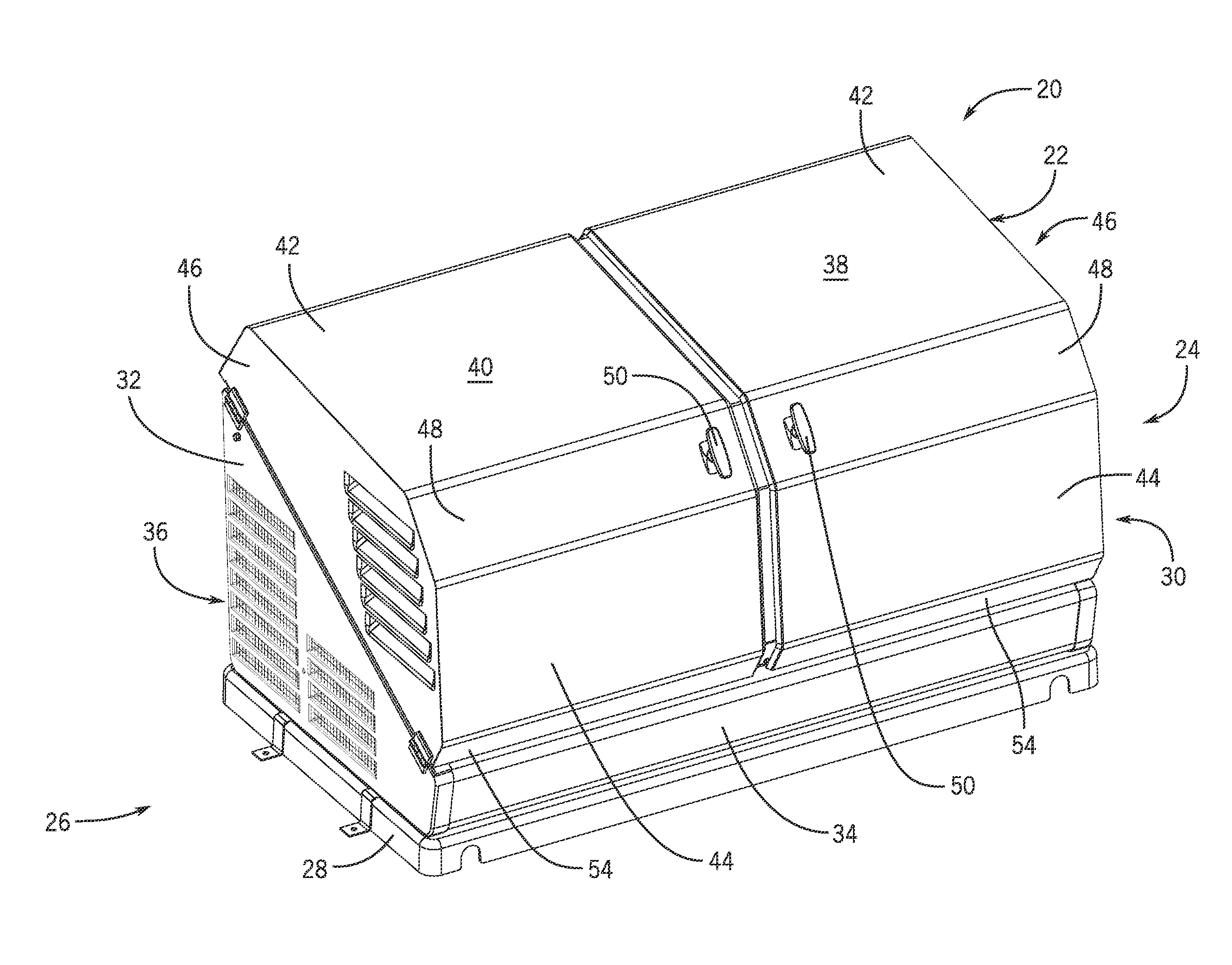
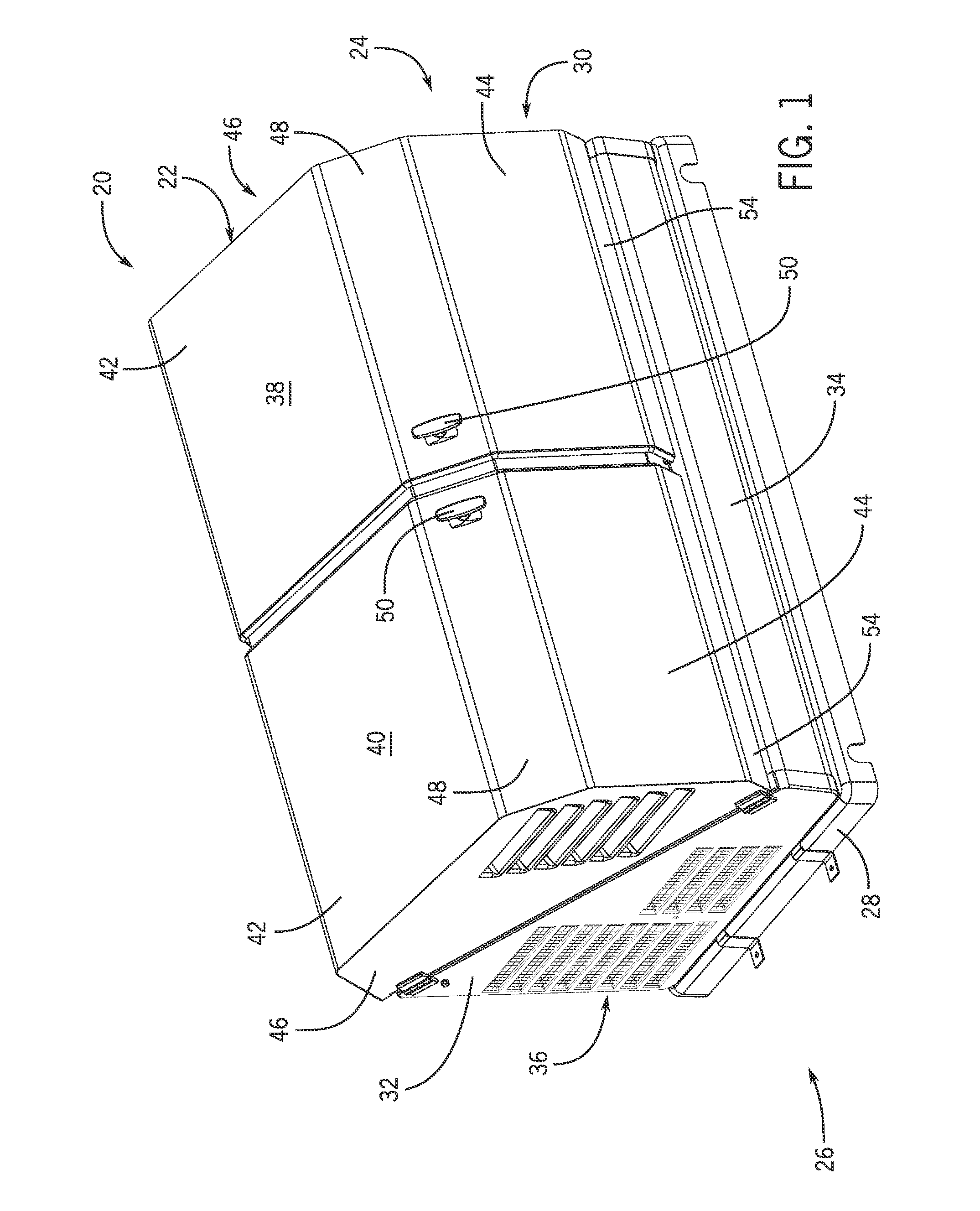
[0024]Referring to FIG. 1, a standby generator 20 is shown, in accordance with an embodiment of the invention. The standby generator 20 produces electrical energy and may deliver the electrical energy to a distribution panel of a home, office, shop, business, or any other building requiring electricity. The standby generator 20 may include an internal combustion engine, an alternator driven by the internal combustion engine, and other associated components. The standby generator 20 includes an enclosure 22 to house the alternator, internal combustion engine, and other associated components. In the embodiment of FIG. 1, the engine and alternator are coupled together in a horizontal shaft arrangement with the engine located toward a first end 24 of the enclosure 22 and the alternator located toward a second end 26 of the enclosure 22.

[0025]The enclosure 22 has a base 28 for supporting the engine and alternator. The enclosure 22 has a first sidewall 30 extending vertically from the bas...


PUM


Abstract

An enclosure for a standby generator includes a frame having a base for supporting an engine and an alternator driven by the engine, a back wall extending generally vertically from the base, and first and second sidewalls extending generally vertically from the base and connected to the back wall at opposite ends of the enclosure, the first and second sidewall each having a top edge, generally sloping downward from the back wall forward. The enclosure also includes first and second doors, each respectively attached to the first and second sidewalls of the frame such that each pivots about the top edge of the first and second sidewalls.

Description

BACKGROUND OF THE INVENTION[0001]Embodiments of the invention relate generally to standby generators and, more particularly, to a standby generator having an enclosure with improved access and serviceability.[0002]Standby generators provide a convenient source of backup power when outages occur in the utility grid. Standby generators may contain a prime mover coupled to a generator to produce electricity. The prime mover often comprises an internal combustion engine configured to operate on natural gas or propane, but can also include operation with diesel, gasoline, or any other available fuel. The generator often comprises an alternator configured to produce electricity for distribution to an electrical panel of a home or building.[0003]Standby generators are typically contained in an enclosure to house the internal combustion engine, alternator, control system and other generator components. The enclosure may protect the generator from the weather and provide insulation against n...

Claims


Application Information

Patent Timeline
Patent Type & Authority Applications(United States)
IPC IPC(8): H02K7/18
CPCH02K7/1815F02B63/04F02B77/13F02B63/044Y02T10/12
Inventor SCHMIT, IANJENISON, LEIGHSOTIRIADES, ALEKO D.SARDER, MARK J.
Owner CHAMPION POWER EQUIP
Learn More