Corrugated energizing ring for use with a split lockdown ring

a technology of energizing rings and lockdown rings, which is applied in the direction of sealing/packing, earthwork drilling and mining, and wellbore/well accessories, etc., can solve the problems of not providing sufficient locking forces, jeopardizing the integrity of the inner and outer wellhead members, etc., to simplify the assembly, simplify the operation, and reduce the relative movement of the inner wellhead member

Active Publication Date: 2016-10-13
GE OIL & GAS PRESSURE CONTROL
View PDF0 Cites 2 Cited by
  • Summary
  • Abstract
  • Description
  • Claims
  • Application Information

AI Technical Summary

Benefits of technology

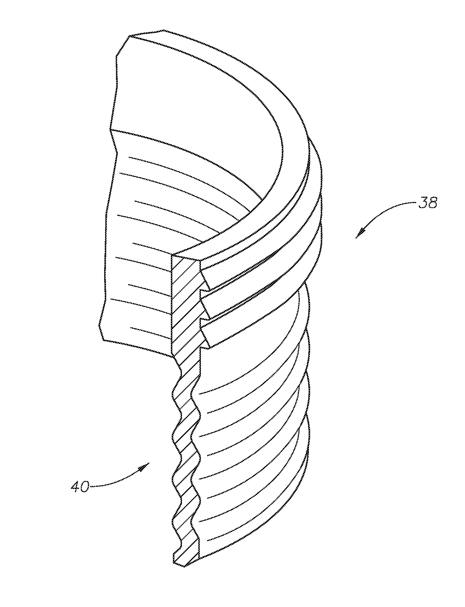
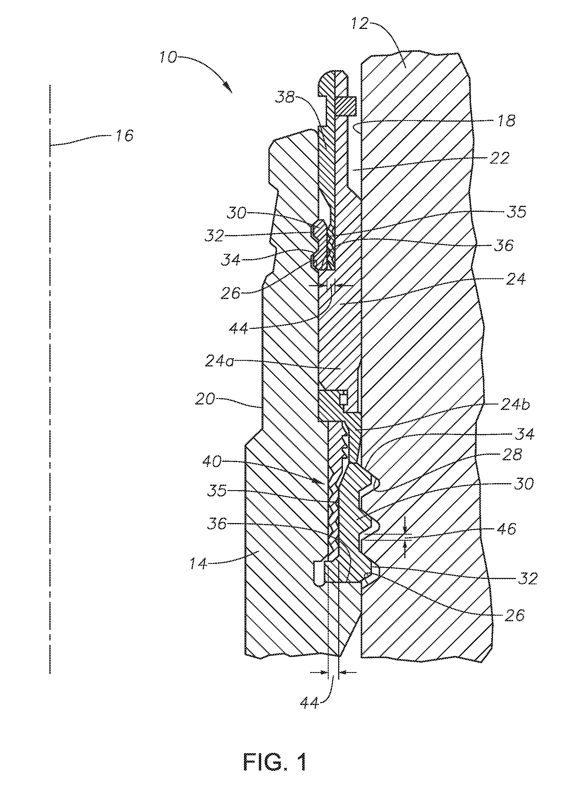
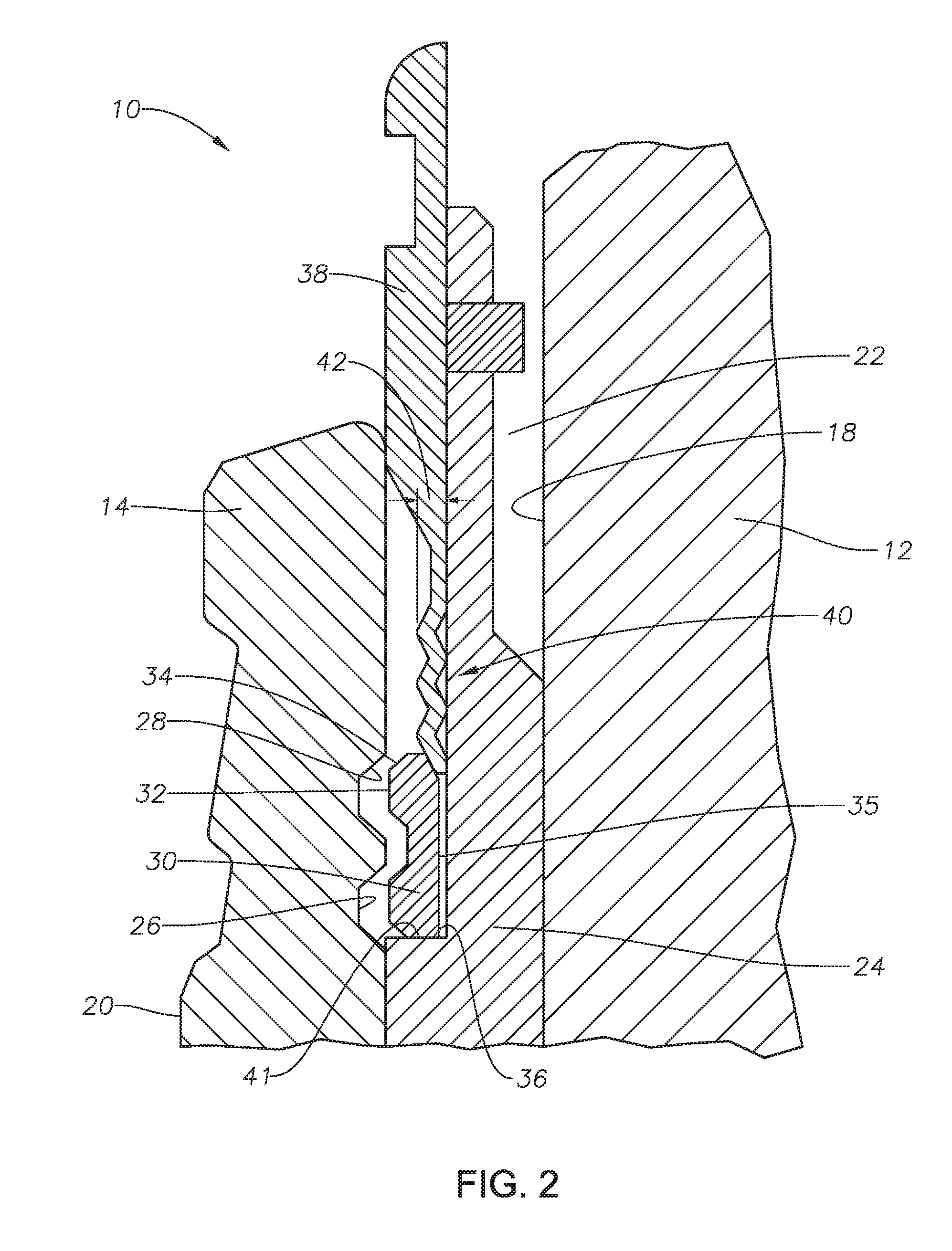
[0010]The methods and systems of the current disclosure provide an energizing ring that minimizes the relative movement of the inner and outer wellhead members. Embodiments described herein provide a positive stop for the energizing ring for controlling the final set position of the energizing ring and do not require an additional lock down device. This can simplify the running of the assembly and provide cost and time savings. Embodiments of this disclosure include an energizing ring with a corrugated profile that allows for sufficient radial interference with the lock ring to ensure contact of the lock ring flanks through the stack up tolerance range while staying within reasonable setting load limits.

Problems solved by technology

This motion can cause wear of the adjacent surfaces, jeopardizing the integrity of the inner wellhead member and the outer wellhead member.
In addition, due to the stack up tolerances, the lock ring may not land in a predicable location and may not provide sufficient locking forces to prevent relative movement between outer and inner wellhead members.

Method used


Image

  • Corrugated energizing ring for use with a split lockdown ring
  • Corrugated energizing ring for use with a split lockdown ring
  • Corrugated energizing ring for use with a split lockdown ring

Examples


Embodiment Construction

[0020]The methods and systems of the present disclosure will now be described more fully hereinafter with reference to the accompanying drawings in which embodiments are shown. The methods and systems of the present disclosure may be in many different forms and should not be construed as limited to the illustrated embodiments set forth herein; rather, these embodiments are provided so that this disclosure will be thorough and complete, and will fully convey its scope to those skilled in the art. Like numbers refer to like elements throughout.

[0021]It is to be further understood that the scope of the present disclosure is not limited to the exact details of construction, operation, exact materials, or embodiments shown and described, as modifications and equivalents will be apparent to one skilled in the art. In the drawings and specification, there have been disclosed illustrative embodiments and, although specific terms are employed, they are used in a generic and descriptive sense...


PUM


Abstract

A wellhead assembly includes first and second wellhead members. An annular lock groove is located on an inner or an outer diameter surface of the first wellhead member. An annular lock ring is supported on an annular shoulder of the second wellhead member and is radially moveable between an unset position and a set position where a locking profile of the annular lock ring engages the annular lock groove. The second wellhead member is positioned concentrically with the first wellhead member, defining an annulus between the first and second wellhead members. An energizing ring is positioned in the annulus and axially movable between an unengaged position and an engaged position. The energizing ring has an engaging portion with a corrugated shape in cross section that is interference fit between the annular lock ring and the second wellhead member when the energizing ring is in the engaged position.

Description

CROSS REFERENCE TO RELATED APPLICATION[0001]This application claims priority to and the benefit of co-pending U.S. Provisional Application Ser. No. 62 / 143,932, filed Apr. 7, 2015, titled “Corrugated Energizing ring For Use With A Split Lockdown Ring,” the full disclosure of which is hereby incorporated herein by reference in its entirety for all purposes.BACKGROUND[0002]1. Field of Disclosure[0003]This invention relates in general to wellhead assemblies, and in particular to energizing rings used to lock down concentric tubular members.[0004]2. Description of Related Art[0005]Wellhead assemblies can include concentric tubular shaped members. Outer and inner wellhead members can be, for example, a wellhead housing, casing hanger, tubing hanger, seal assembly, or other member with a generally ring shaped cross section. Throughout the life of the wellhead assembly, forces within the wellhead assembly can push the inner wellhead member axially up and down. As an example, when the wellhe...

Claims


Application Information

Patent Timeline
Patent Type & Authority Applications(United States)
IPC IPC(8): E21B33/03
CPCE21B33/03E21B33/02E21B33/0422
Inventor TAMOSAITIS, DONALD JAMESLIN, CHIJIE
Owner GE OIL & GAS PRESSURE CONTROL
Why Eureka
Try Eureka