
Image forming device, image forming system, and image forming method

a technology of image forming and forming system, which is applied in the direction of instruments, electrographic process equipment, optics, etc., can solve the problems of poor production efficiency, user may not obtain the desired printing, and no measures are taken to solve the meandering

Active Publication Date: 2016-10-13
KONICA MINOLTA INC
View PDF10 Cites 3 Cited by
  • Summary
  • Abstract
  • Description
  • Claims
  • Application Information

AI Technical Summary

Benefits of technology

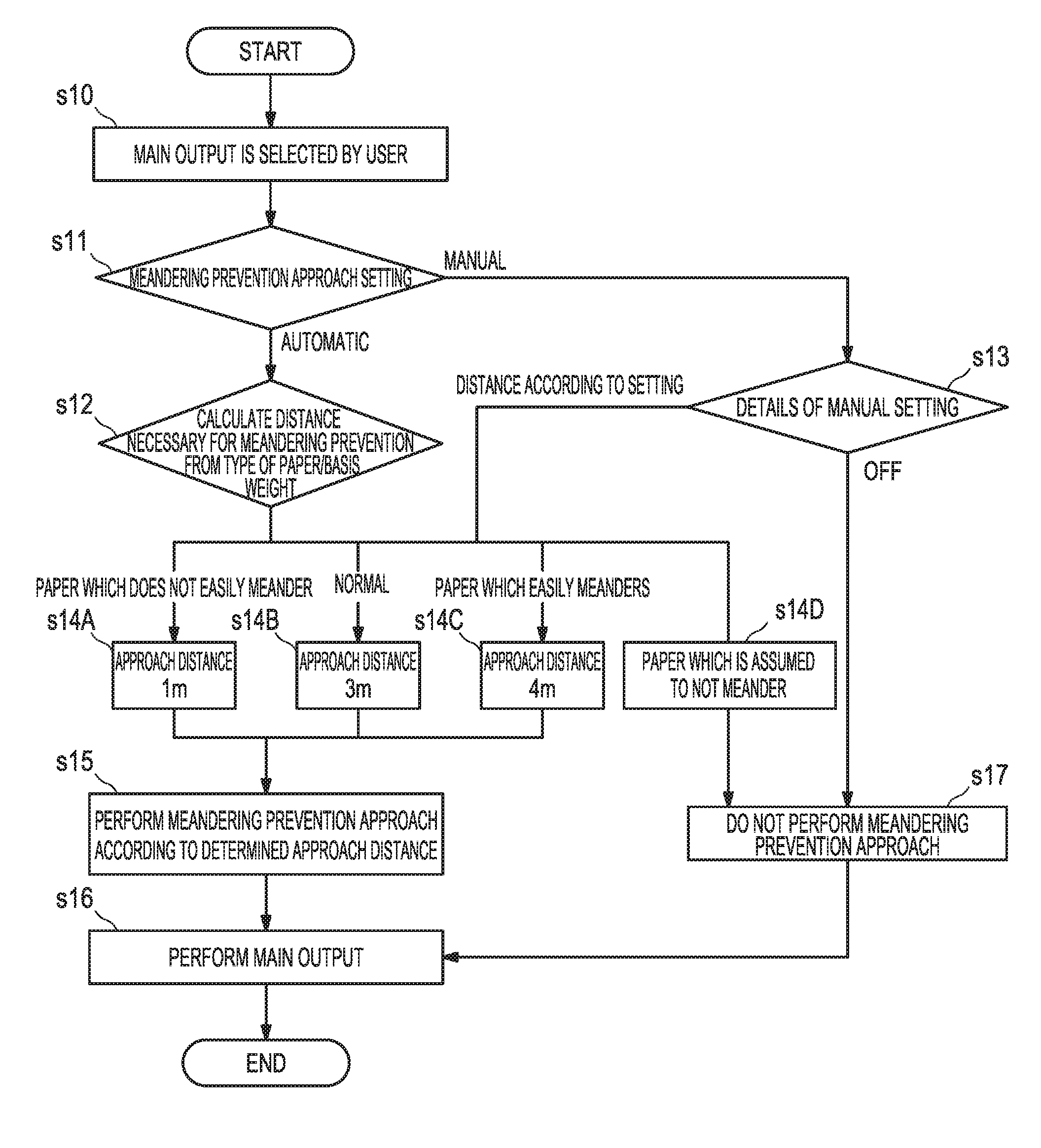
This patent describes a system for printing images on continuous paper. Before printing, the system has a control unit that prevents the paper from meandering (celebrating the starting of a new paper conveyance, and allowing the user to control the level of prevention. This control ensures a smooth, consistent conveyance of the paper along the printing path. The user can turn the prevention feature on or off, or adjust its level, to suit their needs. Overall, this system improves the printing process by ensuring a steady, smooth conveyance of the continuous paper.

Problems solved by technology

In the case of an image forming device that uses continuous paper, the continuous paper sometimes meanders at the time of start of printing, and a user possibly cannot obtain a desired printing result.
H4-182243, when meandering occurs, the device is stopped, and the production efficiency is poor, and no measures are taken to solve the meandering.
On the other hand, according to the technique for solving meandering by conveying paper for a while, it is necessary to check that paper is conveyed without meandering, and the work efficiency is poor.
Furthermore, the technique proposed by Japanese Patent Laid-Open No. 2010-201682 merely intends to reduce the frequency of occurrence of meandering, and does not indicate a method of dealing with meandering once it occurs.

Method used


Image

  • Image forming device, image forming system, and image forming method
  • Image forming device, image forming system, and image forming method
  • Image forming device, image forming system, and image forming method

Examples


Embodiment Construction

[0052]Hereinafter, an embodiment of the present invention will be described with reference to the appended drawings.

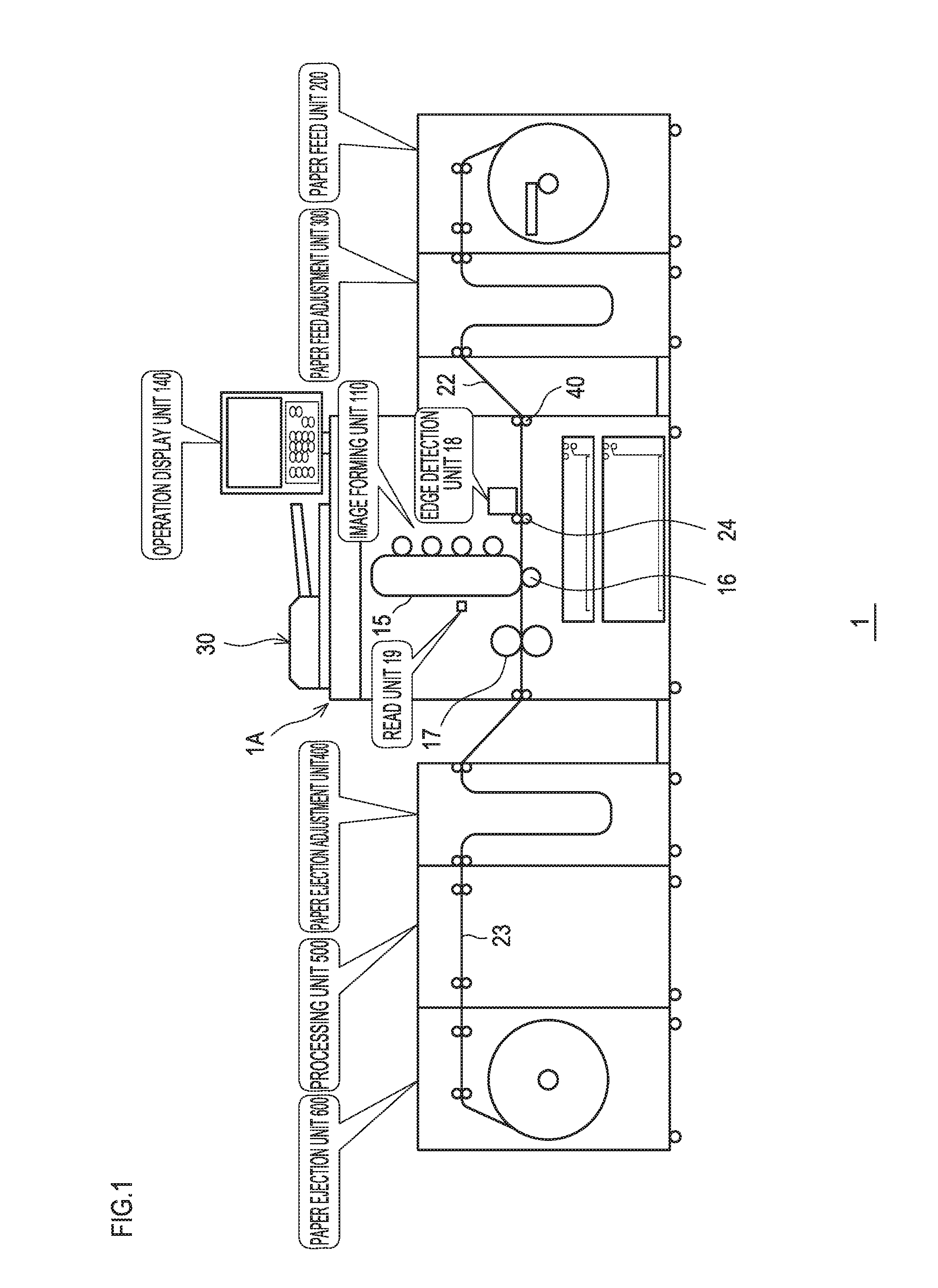
[0053]FIG. 1 shows an image forming device according to an embodiment of the present invention.

[0054]An image forming device 1 includes a device main body 1A provided with an image forming unit, and a paper feed adjustment unit 300 is connected before the device main body 1A, and a paper feed unit 200 is connected before the paper feed adjustment unit 300. Also, a paper ejection adjustment unit 400 is connected on the paper ejection side of the device main body 1A, a processing unit 500 is connected on the paper ejection side of the paper ejection adjustment unit 400, and a paper ejection unit 600 is connected on the ejection side of the processing unit 500.

[0055]Additionally, in the present embodiment, description is given assuming that the image forming device 1 is configured by the device main body 1A and devices connected to the device main body 1A, but the types a...


PUM


Abstract

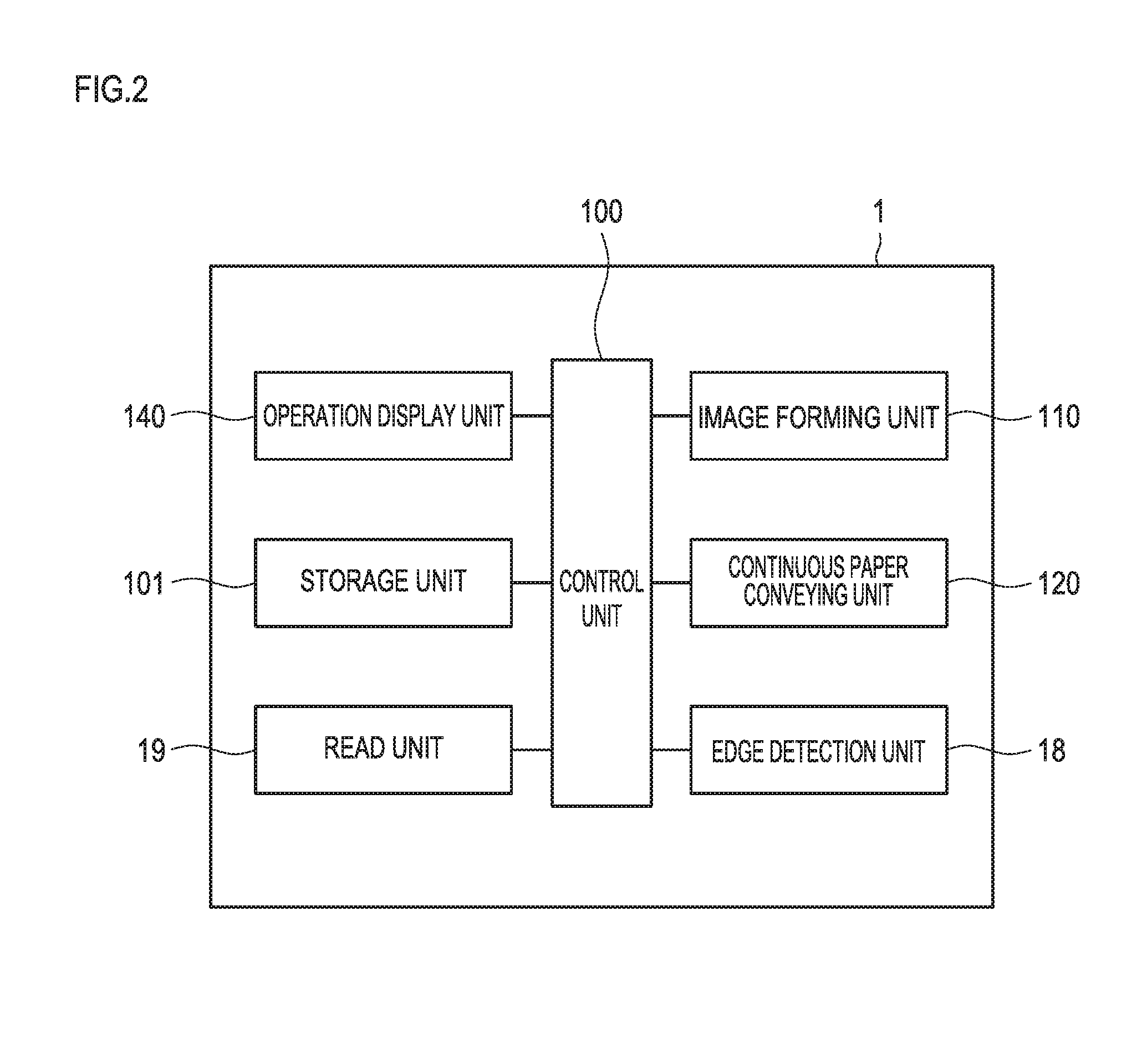
There are included an image forming unit for forming an image on continuous paper, a continuous paper conveying unit for conveying the continuous paper, and a control unit for controlling the image forming unit and the continuous paper conveying unit, wherein, after conveyance is started by the continuous paper conveying unit in printing preparation and before printing is started, the control unit is enabled to perform meandering prevention approach control of stabilizing conveyance of continuous paper that is being conveyed, and allows switching between performance and non-performance of the meandering prevention approach control and / or changing a level of the meandering prevention approach.

Description

CROSS-REFERENCE TO RELATED APPLICATIONS[0001]The present application claims priority under 35 U.S.C. §119 to Japanese Patent Application No. 2015-081285, filed Apr. 10, 2015. The contents of this application are incorporated herein by reference in their entirety.BACKGROUND OF THE INVENTION[0002]1. Field of the Invention[0003]The present invention relates to an image forming device, an image forming system, and an image forming method which enable printing on continuous paper.[0004]2. Description of the Related Art[0005]In the case of an image forming device that uses continuous paper, the continuous paper sometimes meanders at the time of start of printing, and a user possibly cannot obtain a desired printing result. There is a technique for preventing meandering of paper by reading the position of a paper edge by a sensor and by detecting occurrence of meandering (see Japanese Patent Laid-Open No, H4-182243). This technique relates to a printing device for avoiding meandering which...

Claims


Application Information

Patent Timeline
Patent Type & Authority Applications(United States)
IPC IPC(8): G03G15/00
CPCG03G15/6529G03G15/55G03G15/6517G03G15/6558
Inventor FURUKAWA, HIROSHI
Owner KONICA MINOLTA INC
Learn More