Infusion needle, infusion needle unit, and fluid infusion apparatus
a fluid infusion apparatus and needle technology, applied in the direction of needles, intravenous devices, other medical devices, etc., can solve the problems of clogging the flow path, affecting the smooth infusion of fluid such as chemical into the living body, etc., and achieve the effect of smooth infusion of fluid
- Summary
- Abstract
- Description
- Claims
- Application Information
AI Technical Summary
Benefits of technology
Problems solved by technology
Method used
Image
Examples
first embodiment
Overview of Fluid Infusion Apparatus 1
[0033]A fluid infusion apparatus 1 according to the first embodiment of the invention is used for e.g. periodic infusion of a chemical (fluid) of insulin or the like into a living body.
Configuration of Fluid Infusion Apparatus 1
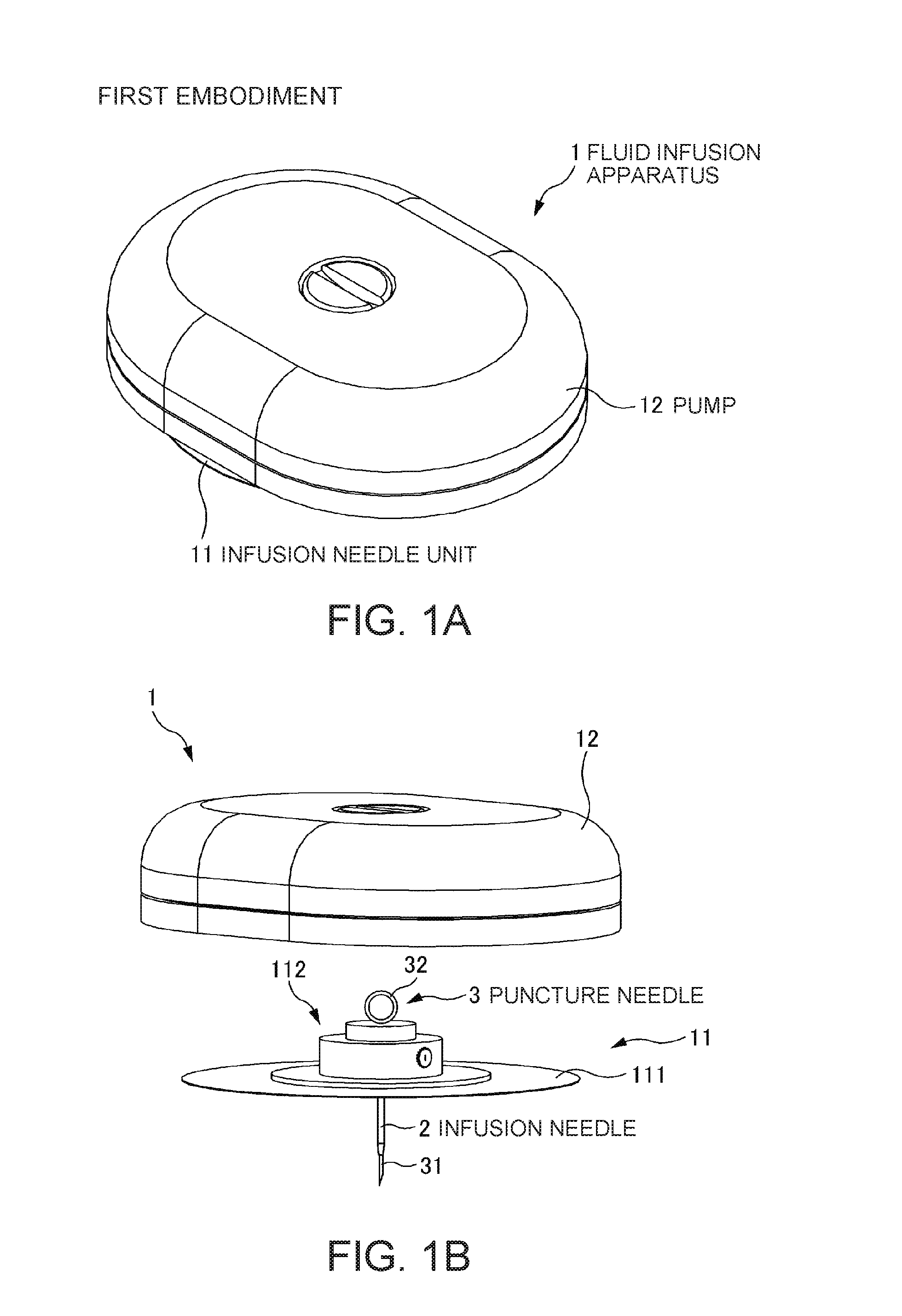
[0034]A configuration of the fluid infusion apparatus 1 will be explained with reference to FIGS. 1A and 1B.
[0035]FIGS. 1A and 1B show one configuration example of the fluid infusion apparatus 1 according to the first embodiment of the invention, and FIG. 1A is a perspective view and FIG. 1B is an exploded perspective view.
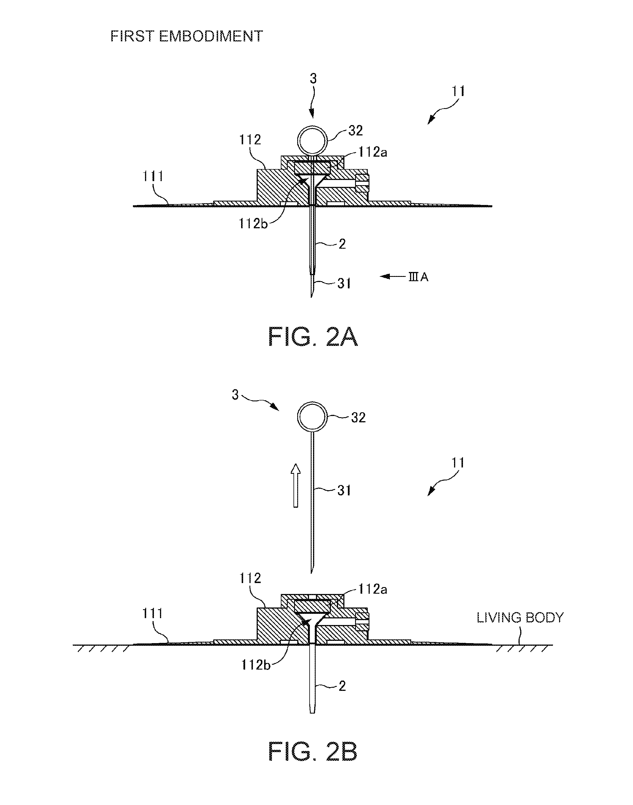
[0036]The fluid infusion apparatus 1 includes an infusion needle unit 11 having an infusion needle 2 and a puncture needle 3, and a pump 12 that infuses a fluid into the infusion needle 2. The infusion needle unit 11 and the pump 12 can be separated as shown in FIG. 1B and, for use, integrally combined as shown in FIG. 1A. Note that, in the fluid infusion apparatus 1, the infusion needle unit 11 and the...
modified example
[0067]Next, a configuration of a infusion needle 2A according to a modified example of the invention will be explained with reference to FIG. 7.
[0068]FIG. 7 is a sectional view in an extension direction of the infusion needle 2A according to the modified example. In FIG. 7, the component elements in common with the infusion needle 2 according to the first embodiment have the same signs and their explanation will be omitted. As below, this applies to the second, the third, and the fourth embodiments.
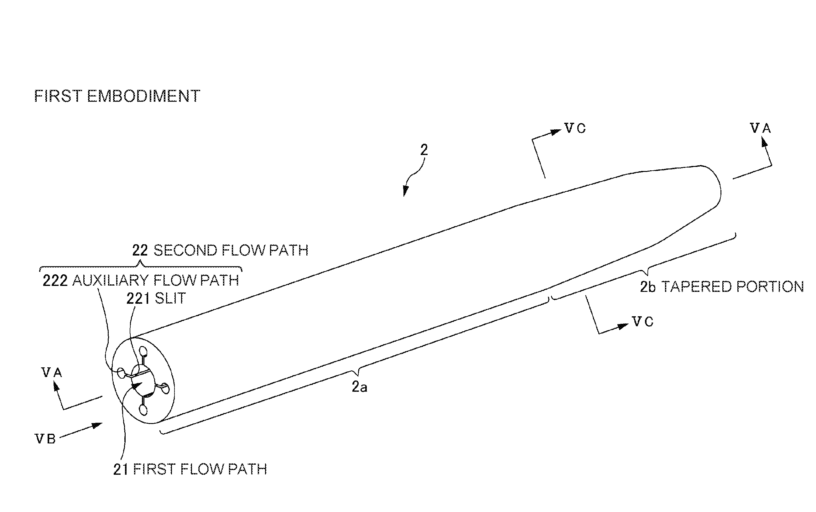
[0069]The infusion needle 2A according to the modified example has a first flow path 21 and second flow paths 23 inside like the infusion needle 2 according to the first embodiment, and includes a base portion 2a and a tapered portion 2b. Note that the configurations of the second flow paths 23 are different from the configurations of the second flow path 22 according to the first embodiment. Specifically, in the second flow path 23, a slit 223 has a depth gradually shallower toward the t...
second embodiment
[0072]Next, a configuration of an infusion needle 2B according to the second embodiment of the invention will be explained with reference to FIGS. 8A and 8B. The infusion needle 2B according to the embodiment can be applied to the fluid infusion apparatus 1 and the infusion needle unit 11 according to the first embodiment.
[0073]FIGS. 8A and 8B show a configuration example of the infusion needle 2B according to the second embodiment of the invention, and FIG. 8A is a perspective view and FIG. 8B is a view from a direction of arrow VIIIB in FIG. 8A.
[0074]In the infusion needle 2B according to the embodiment, configurations of second flow paths are different from the configurations of the second flow paths 22 of the infusion needle 2 according to the first embodiment. Specifically, the second flow path of the infusion needle 2B includes only a slit 221 communicating with a first flow path 21 along the first flow path 21. That is, the infusion needle 2B has no auxiliary flow path. In th...
PUM
 Abstract
Description
Claims
Application Information
 - R&D
- Intellectual Property
- Life Sciences
- Materials
- Tech Scout
- Unparalleled Data Quality
- Higher Quality Content
- 60% Fewer Hallucinations
Browse by: Latest US Patents, China's latest patents, Technical Efficacy Thesaurus, Application Domain, Technology Topic, Popular Technical Reports.
© 2025 PatSnap. All rights reserved.Legal|Privacy policy|Modern Slavery Act Transparency Statement|Sitemap|About US| Contact US: help@patsnap.com


