
Nail machine with effort-saving mechanism

a technology of effort-saving mechanism and nail machine, which is applied in the field of nail machine, can solve the problems of inconvenient use and large space occupation of nail gun, and achieve the effects of less pressing force, convenient torque conversion efficiency, and greater output force or torque outpu

Inactive Publication Date: 2016-10-20
APEX MFG
View PDF19 Cites 11 Cited by
  • Summary
  • Abstract
  • Description
  • Claims
  • Application Information

AI Technical Summary

Benefits of technology

The present invention is a nail machine with a linkage assembly that converts torque to produce greater output force with less pressing force. It has at least two pivots that enhance torque conversion efficiency. The angle between the pressing lever and a horizontal plane is smaller, improving mechanical function and making the nail machine easier and more effort-saving to use.

Problems solved by technology

The increase of the length of the pressing member and the included angle between the pressing member and the staple gun make a volume of the nail gun increase, so the nail gun occupies much space and may be inconvenient for the user to use.

Method used


Image

  • Nail machine with effort-saving mechanism
  • Nail machine with effort-saving mechanism
  • Nail machine with effort-saving mechanism

Examples


Embodiment Construction

[0019]The present invention will be clearer from the following description when viewed together with the accompanying drawings, which show, for purpose of illustrations only, the preferred embodiment in accordance with the present invention.

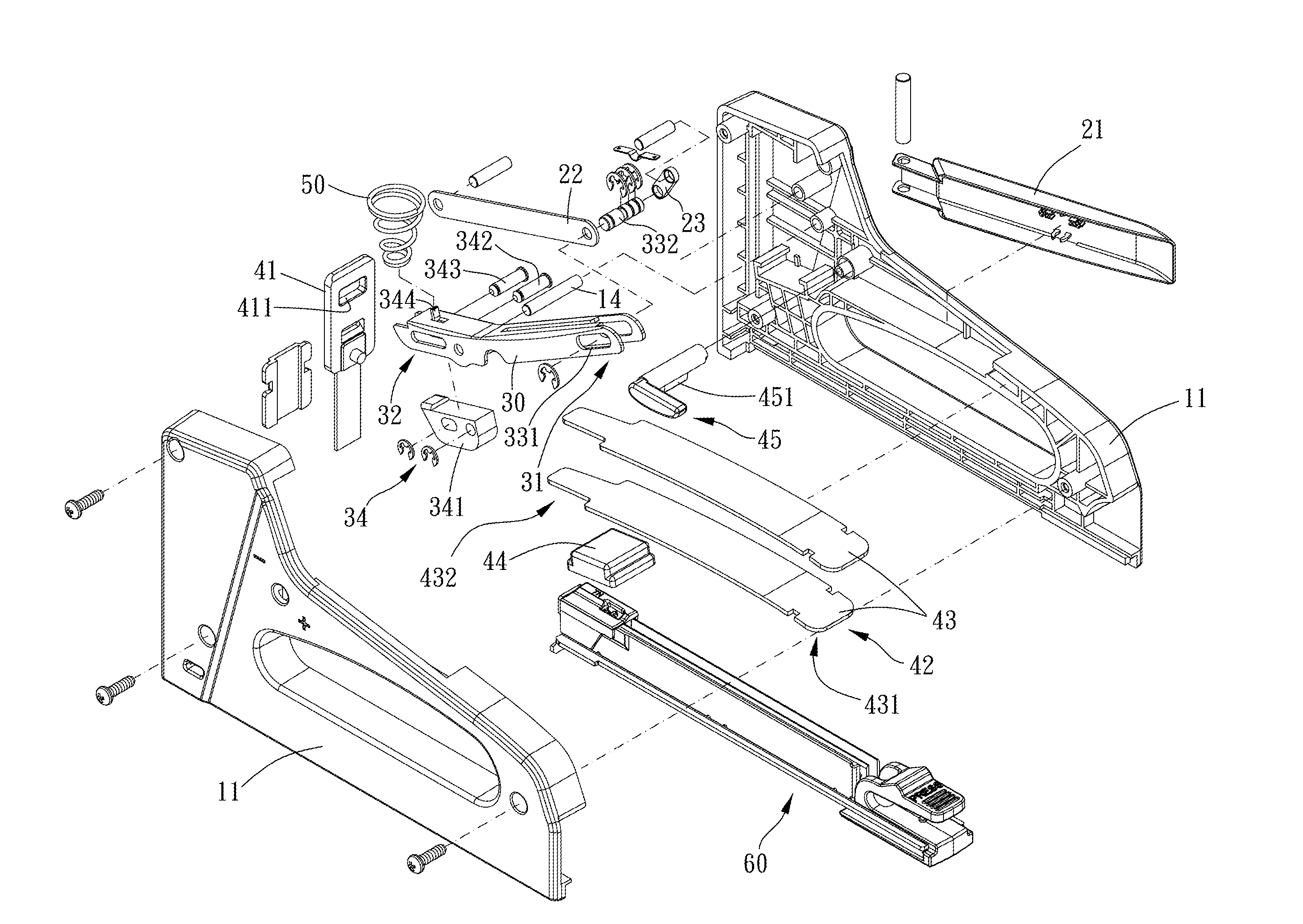
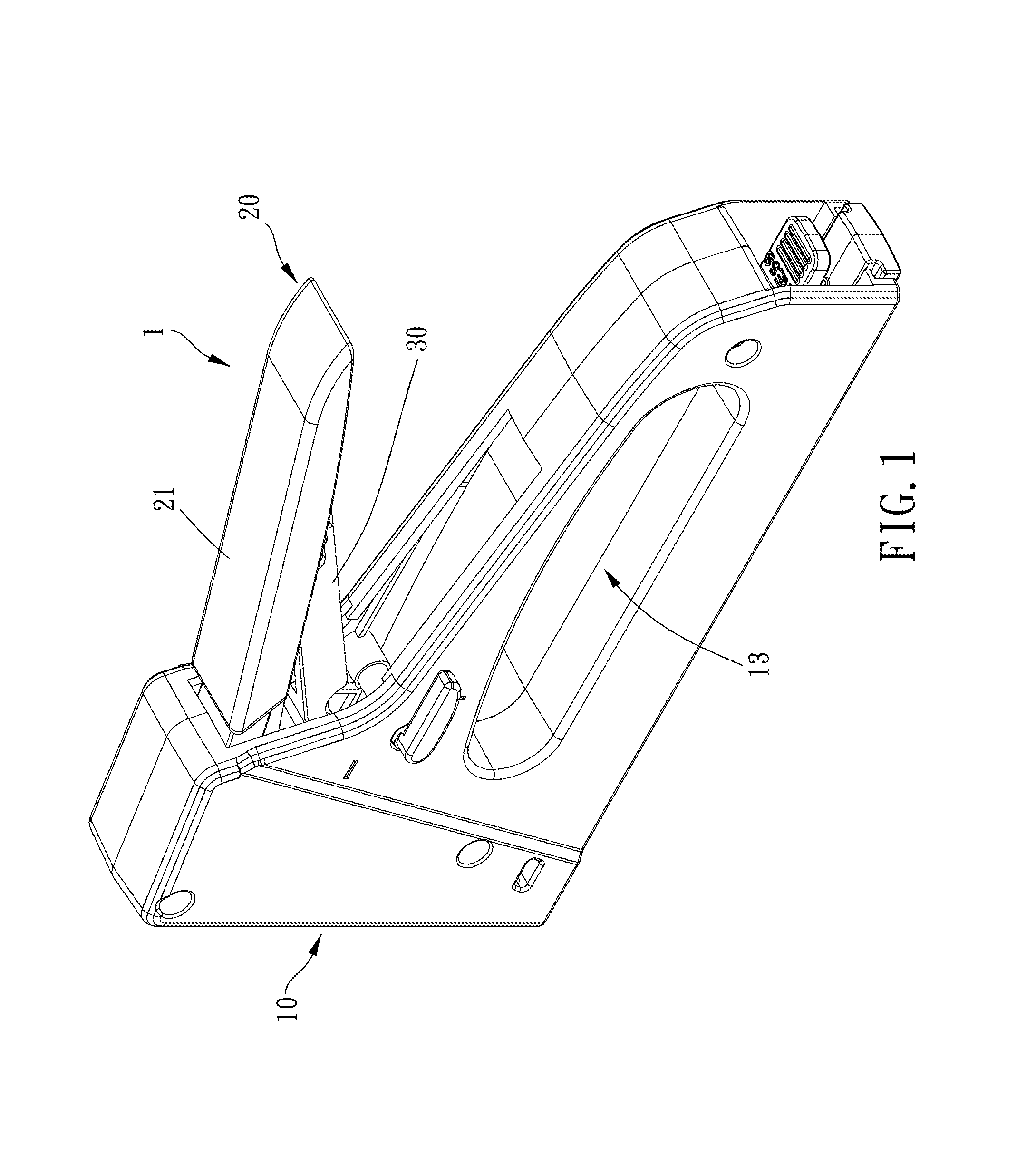
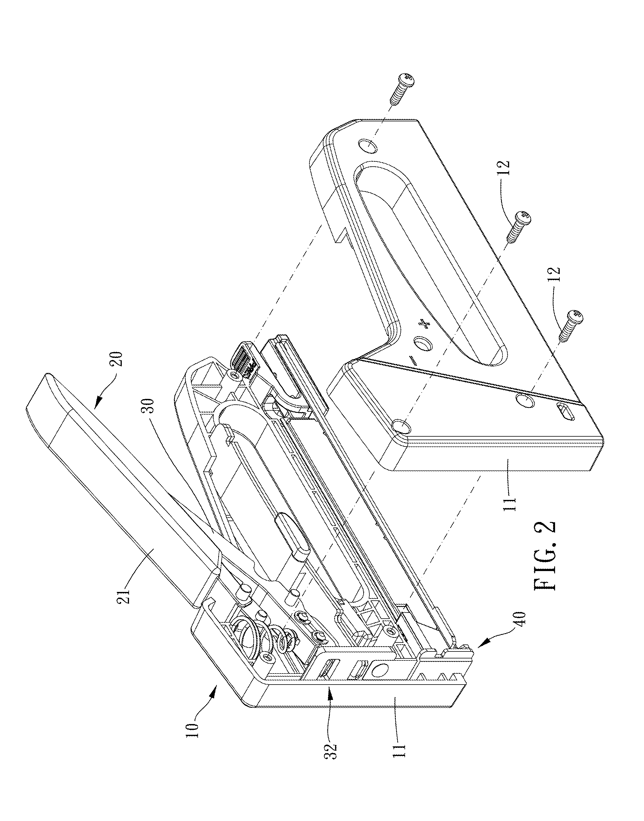
[0020]Please refer to FIGS. 1 to 7 for a preferred embodiment of a nail machine with effort-saving mechanism 1 of the present invention. The nail machine with effort-saving mechanism 1 includes a shell body 10, an operating mechanism 20, an actuating member 30 and a striking force accumulating mechanism 40.

[0021]The shell body 10 includes two shells 11 which can be assembled with each other, and the two shells 11 can be fixedly assembled with each other via a screw 12. The shell body 10 further includes a grip portion 13 for a user to grip on or apply force to. The operating mechanism 20 is movably pivoted to the shell body 10. The operating mechanism 20 is a linkage assembly and at least includes a pressing lever 21, a driving rod 22 and a linka...


PUM


Abstract

A nail machine with effort-saving mechanism is provided, including: a shell body; an operating mechanism, disposed on the shell body and including a pressing lever, a driving rod and a linkage, the operating mechanism provided for being operated to move between a first position and a second position; an actuating member, two ends thereof having a sliding portion and an engaging portion respectively; a striking force accumulating mechanism, including a striking board and a force accumulating member, the striking board being movable between an initial position and a releasing position; wherein when the operating mechanism moves toward the second position, the engaging portion is engaged with the striking board, and the striking board moves toward the releasing position; when the operating mechanism is in the second position, the engaging portion is detached from the striking board, and the striking board moves toward the initial position.

Description

BACKGROUND OF THE INVENTION[0001]1. Field of the Invention[0002]The present invention relates to a nail machine, and more particularly to a nail machine with effort-saving mechanism.[0003]2. Description of the Prior Art[0004]Usually, a conventional nail gun as disclosed in TWI413578 at least includes a pressing member, a shell, a striking board and an actuating portion. The shell includes a striking slot, and the striking board is movable along the striking slot. When the pressing member moves relative to the shell, the actuating portion actuates the striking board to move along the striking slot and strike a staple.[0005]However, the pressing member of the above-mentioned structure usually has a longer length in order to produce greater force, and an included angle between the pressing member and the nail gun needs to be greater so as to allow a user to press the pressing member easily. The increase of the length of the pressing member and the included angle between the pressing me...

Claims


Application Information

Patent Timeline
Patent Type & Authority Applications(United States)
IPC IPC(8): B25C5/11B25C5/16
CPCB25C5/1606B25C5/11
Inventor HU, PO-HUNG
Owner APEX MFG
Learn More