System and method for bidirectional communication between stylus and stylus sensor controller

a technology of stylus and sensor controller, which is applied in the field of system and method for bidirectional communication between stylus and stylus sensor controller, can solve the problems of slow response time of sensor controller, sensor controller may not be able to quickly acquire capability information, and inability to support different and expanding variations of stylus capabilities and functions

Active Publication Date: 2016-10-20
WACOM CO LTD
View PDF4 Cites 64 Cited by
  • Summary
  • Abstract
  • Description
  • Claims
  • Application Information

AI Technical Summary

Benefits of technology

[0008]Embodiments of the invention offer a technical solution that allows a sensor controller to quickly determine the capability information of one or more active styluses that enter the sensing zone to thereby start bidirectional communication with the styluses. The embodiments are particularly suited to provide a universal stylus-sensor controller interface, which supports different active styluses having different capability information.

Problems solved by technology

Typically, a data format used in communication from a stylus to a sensor controller is rigidly configured in a given stylus-sensor system and incapable of supporting different and expanding variations of stylus capabilities and functions.
In a typical situation where one or more styluses are constantly entering and exiting the sensing zone of the sensor controller, the sensor controller may not be able to quickly acquire the capability information of each entering stylus to start communication with the stylus in a manner appropriate for the stylus's particular capability.
This may lead to slow response time of the sensor controller and hence delay in establishing communication between the sensor controller and the active stylus.
For example, the sensor controller may not be able to promptly receive pen orientation data from a stylus, even when the stylus is fully capable of transmitting such orientation data, simply because the sensor controller cannot quickly ascertain the stylus's orientation detection capability.

Method used


Image

  • System and method for bidirectional communication between stylus and stylus sensor controller
  • System and method for bidirectional communication between stylus and stylus sensor controller
  • System and method for bidirectional communication between stylus and stylus sensor controller

Examples


Embodiment Construction

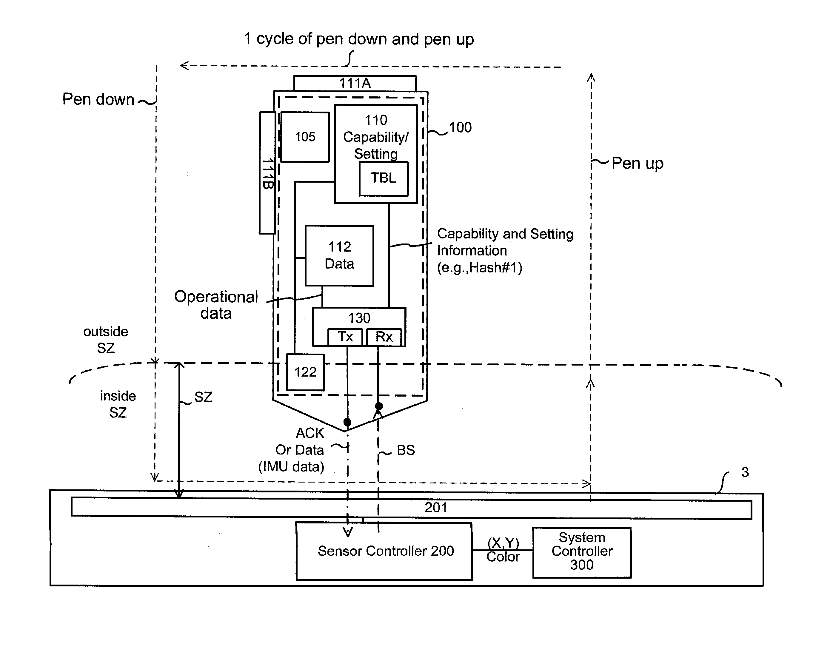
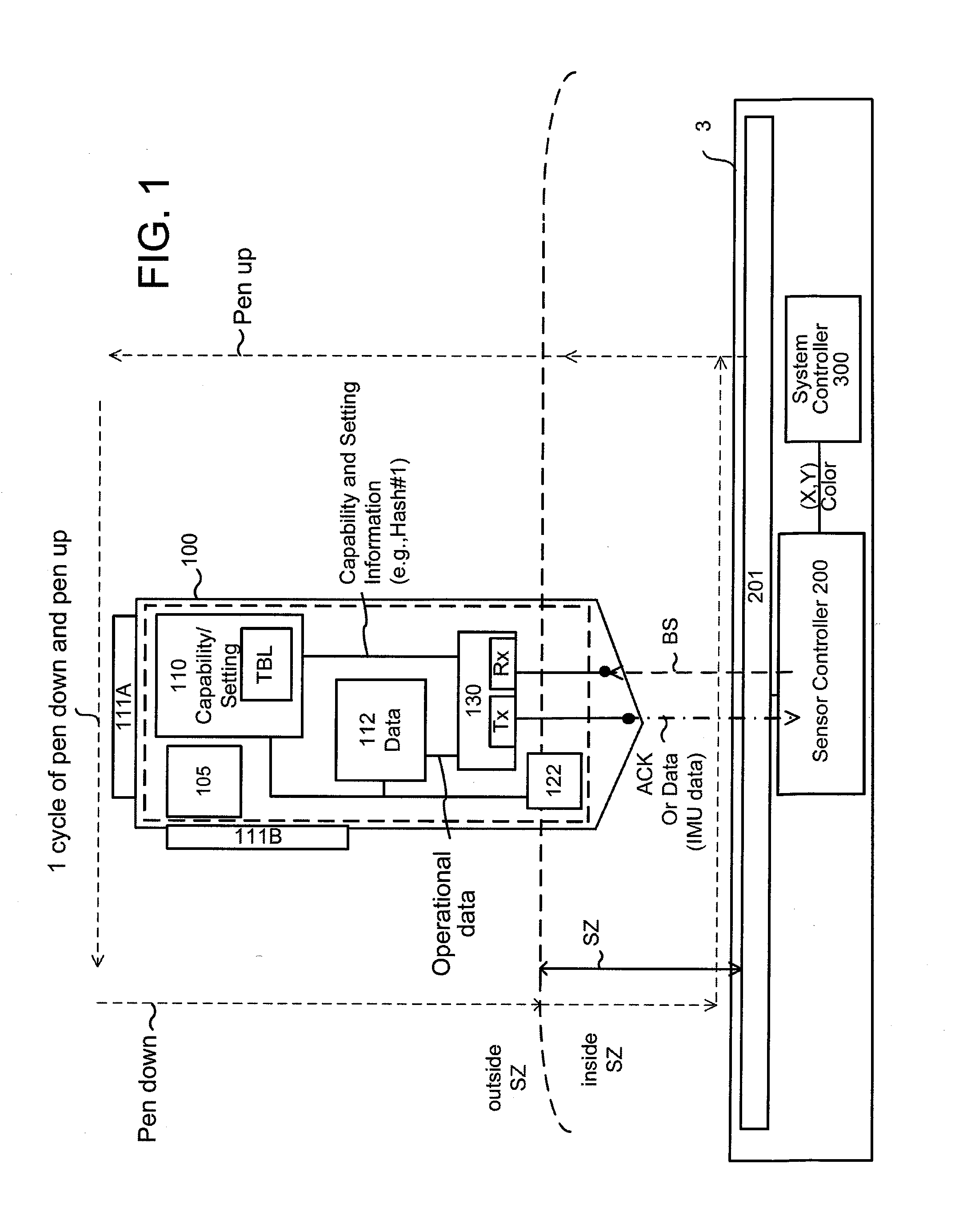
[0038]FIG. 1 illustrates an overall system including an active stylus 100 and an electronic device (e.g., PC, tablet computer, smartphone) 3. The electronic device 3 includes a sensor 201, a sensor controller 200 coupled to the sensor 201, and a system controller (host processor) 300 of the electronic device 3 coupled to the sensor controller 200.

[0039]The electronic device 3, such as a PC, tablet computer, smartphone, etc., typically includes a screen that underlies or overlies the sensor 201, and a user operates the active stylus 100 to handwrite text and graphics on the screen. As used herein, an active stylus is a stylus that contains electronics and a power source 105, such as a battery or a parasitic energy conduit. The sensor 201 may be any suitable stylus sensitive sensor known in the art, such as a capacitive touch / stylus sensor, resistive touch / stylus sensor, electromagnetic resonance stylus sensor, optical stylus sensor, ultrasonic stylus sensor, etc. Some are stylus sens...


PUM


Abstract

A method is provided to interface an active stylus with a sensor controller, wherein the sensor controller is coupled to a sensor configured to receive input from the active stylus. In the method the sensor controller defines data frames consisting of more than one time slot usable for receiving packets from the stylus. The active stylus transmits, in response to a request from the sensor controller, a signal including stylus capability information. The sensor controller determines, based on the stylus capability information, a downlink time slot allocation for use by the active stylus to transmit packets to the sensor controller. The sensor controller transmits the downlink time slot allocation to the active stylus.

Description

CROSS-REFERENCE TO RELATED APPLICATIONS[0001]The present application claims priority to U.S. Provisional Patent Application No. 62 / 149,907, entitled “Position Input Method, Position Input System, Sensor Controller and Stylus,” filed Apr. 20, 2015; U.S. Provisional Patent Application No. 62 / 162,527, entitled “Position Input Method, Position Input System, Sensor Controller and Stylus,” filed May 15, 2015; U.S. Provisional Patent Application No. 62 / 243,427, entitled “Position Input Method, Position Input System, Sensor Controller and Stylus,” filed Oct. 19, 2015; and U.S. Provisional Patent Application No. 62 / 291,373, entitled “System and Method for Bidirectional Communication Between Stylus and Stylus Sensor Controller,” filed Feb. 4, 2016, the entirety of which are hereby incorporated by reference.BACKGROUND[0002]1. Technical Field[0003]The present application relates to an active stylus, a sensor controller for a stylus sensor, and a position input system and method based on such st...

Claims


Application Information

Patent Timeline
Patent Type & Authority Applications(United States)
IPC IPC(8): G06F3/0354G06F3/0346G06F3/044H04W72/04G06F3/038
CPCG06F3/03545H04W72/0446G06F3/0346G06F3/0383G06F3/044H04W72/042G06F3/0418H04W4/026G06F3/0414G06F3/0416G06F3/03547G06F3/0446G06F3/0442G06F3/04162
Inventor FLECK, DAVID CHARLESYAMAMOTO, SADAO
Owner WACOM CO LTD
Why Eureka
Try Eureka