Accommodating intraocular lens

a technology for accommodating intraocular lenses and lenses, applied in intraocular lenses, medical science, prosthesis, etc., can solve the problems of inability to accurately exert the accommodation function of the intraocular lens arranged therein, inability to accurately transmit the contraction and relaxation of the ciliary muscles of the ciliary bodies, and inability to accurately convert. , to achieve the effect of reducing the diameter of the lens equator, moderate strength and high accuracy

Active Publication Date: 2016-10-27
MIRAI EYE INC
View PDF11 Cites 27 Cited by
  • Summary
  • Abstract
  • Description
  • Claims
  • Application Information

AI Technical Summary

Benefits of technology

[0031]According to the present invention, due to the biasing force of the connecting portion, the front supporting portion presses the inner surface of the anterior capsule and the rear supporting portion presses the inner surface of the posterior capsule. As a result, the peripheral portion of the lens equator tries to extend and expand in the front-back direction and the lens equator expands. At the same time, the lens equator moves centripetally and the diameter of the lens equator decreases. Due to this, the Zinn's zonules are pulled in both directions toward the lens capsule and the ciliary bodies and tension of moderate strength is continuously applied to the Zinn's zonules. As a result, moderate tension is applied to the lens capsule. Thus, the Zinn's zonules can transmit the slight contraction and relaxation of the ciliary muscles of the ciliary bodies to the lens capsule with high accuracy, and accordingly, the accommodation function of the optical portion disposed th...

Problems solved by technology

Therefore, the slight contraction and relaxation of the ciliary muscles of the ciliary bodies are not accurately transmitted to the lens capsule and are not accurately converted to the movement of the optical portion in the front-back direction.
Moreover, it is difficult to accurately exert the accommodation function of the intraocular lens arranged therein.
However, it is difficult to continuously maintain tension of moderate strength in the Zinn's zonules.
For this...

Method used


Image

  • Accommodating intraocular lens
  • Accommodating intraocular lens
  • Accommodating intraocular lens

Examples


first embodiment

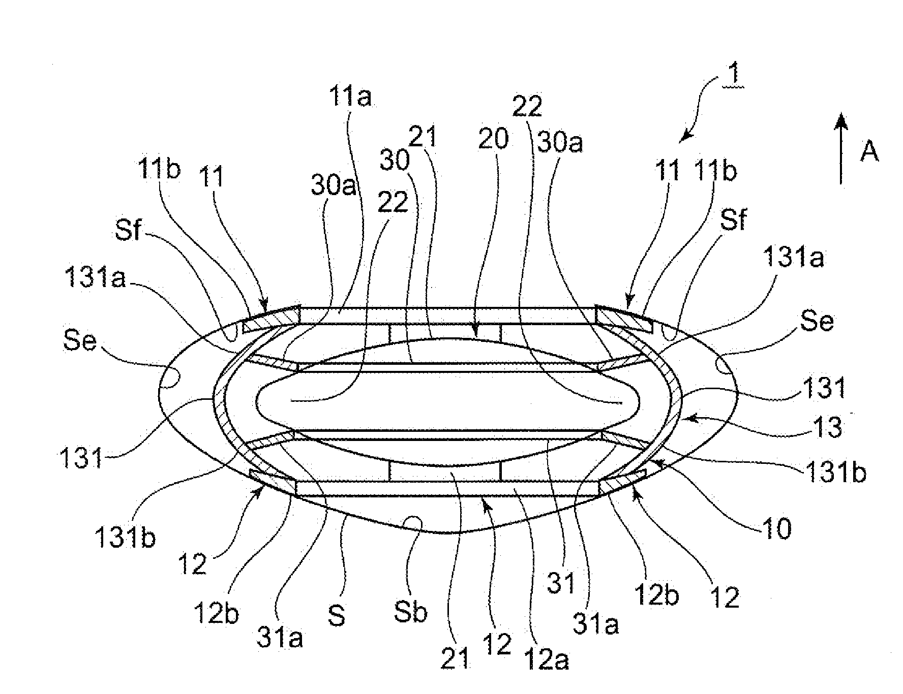
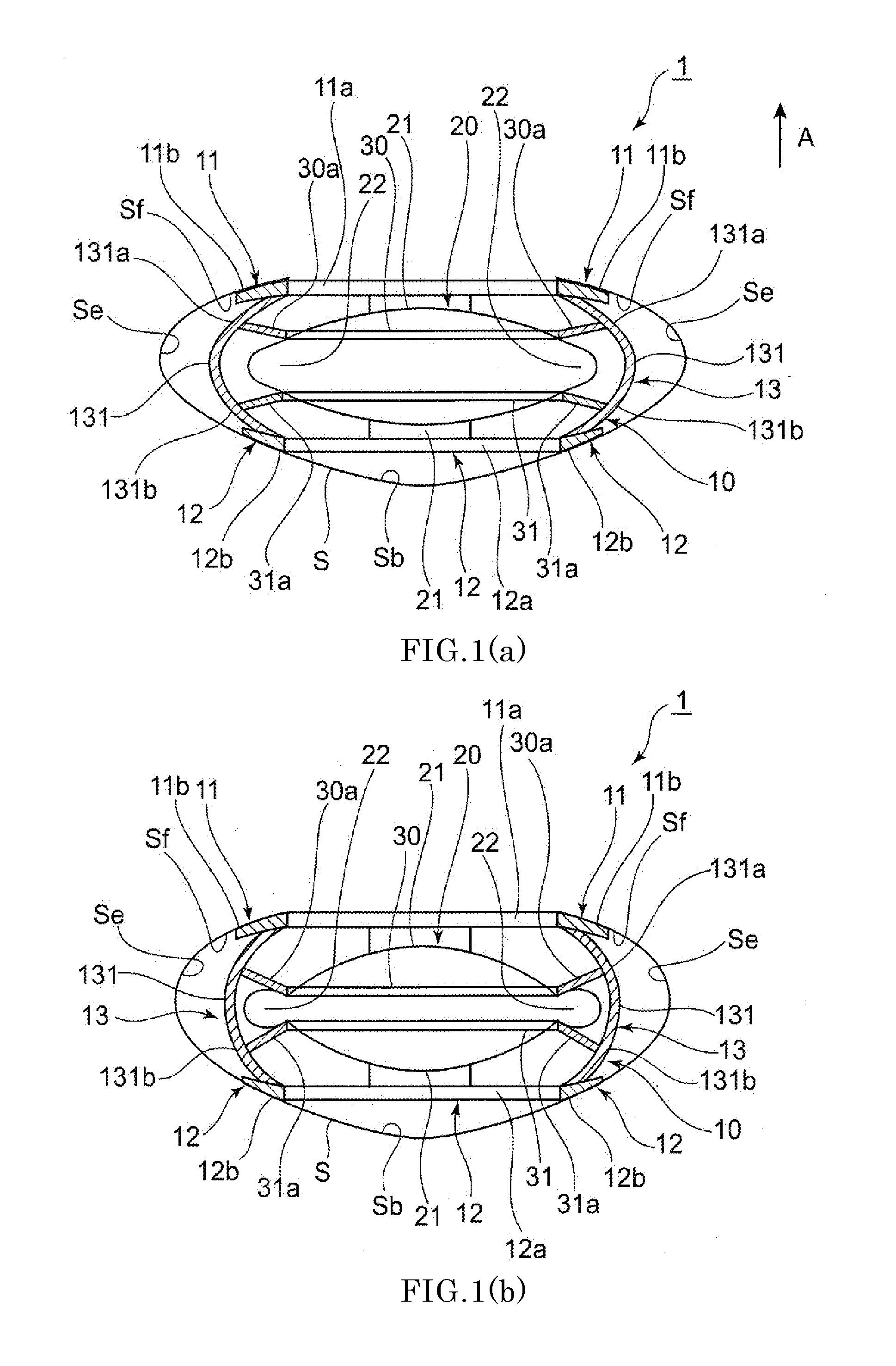
[0039]Next, a first embodiment of an accommodating intraocular lens according to the present invention will be described with reference to FIG. 1.

[0040]An accommodating intraocular lens 1 includes a lens capsule expanding device (hereinafter referred to as a device 10) and an optical portion 20 disposed inside the device 10. In the following description, the direction indicated by arrow A illustrated in the drawings is defined as a front side and the opposite direction is defined as a rear side.

[Device Configuration]

[0041]As illustrated in FIG. 1, the device 10 is arranged in the lens capsule S of which the anterior capsule Sf is incised during ophthalmic surgeries such as an extracapsular extraction surgery performed as a part of a cataract surgery, a refractive correction surgery, or a presbyopia correction surgery. As illustrated in FIG. 1, the device 10 includes a front supporting portion 11 positioned on the front side in the lens capsule S, a rear supporting portion 12 positio...

second embodiment

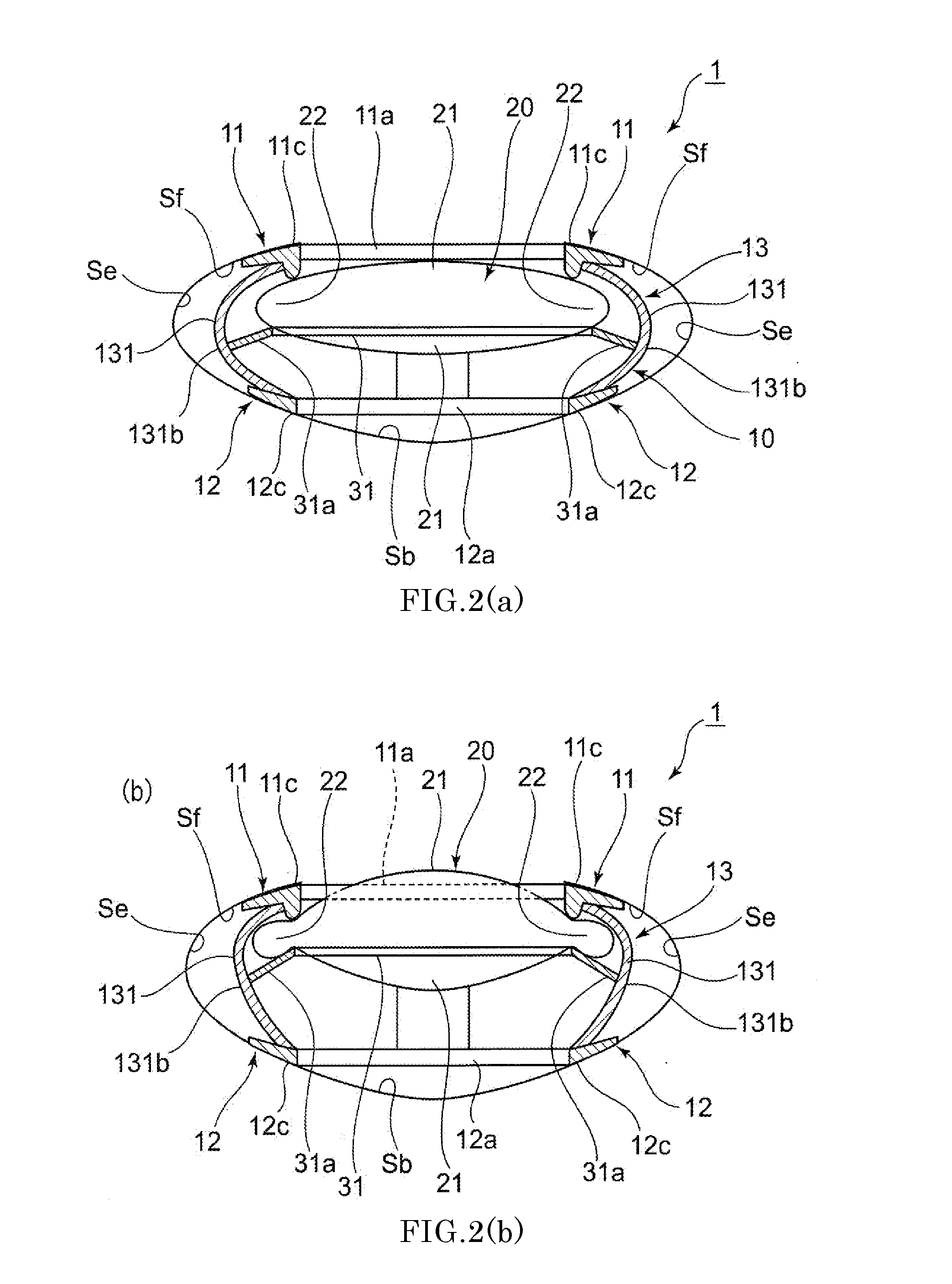
[0059]Next, a second embodiment of the accommodating intraocular lens 1 according to the present invention will be described with reference to FIG. 2.

[0060]The optical portion 20 on the front surface is in contact with the inner circumferential portion 11c of the front supporting portion 11 of the lens capsule expanding device 10 whereas the rear ring member 31 on the rear surface is provided in such a manner of being parallel to the circumferential portion 22 of the optical portion 20. The front ring member 30 is not provided unlike the first embodiment.

[0061]Therefore, as illustrated in FIG. 2(a), during distance vision (non-focus accommodation), when the front supporting portion 11 and the rear supporting portion 12 move in the direction closer to each other and the degree of expansion of the connecting portion 13 in the radially outward direction increases, the lower portion 131b of the connecting piece 131 moves in the radially outward direction. In this case, the lateral branc...

third embodiment

[0066]Next, a third embodiment of the accommodating intraocular lens 1 according to the present invention will be described with reference to FIG. 3.

[0067]As illustrated in FIG. 3, the device 10 according to the present embodiment includes a first connecting portion 132 that connects the outer circumferential portions of the front supporting portion 11 and the rear supporting portion 12 and a second connecting portion 133 that connects the inner circumferential portions of the front supporting portion 11 and the rear supporting portion 12. The second connecting portion 133 further includes a front ring connecting portion 133A and a rear ring connecting portion 133B arranged alternately along the circumferential direction.

[0068]The front ring connecting portion 133A includes a plurality of connecting pieces provided at equal intervals along the circumferential direction of the front supporting portion 11 and the rear supporting portion 12, a bent portion 133a is formed at a position ...


PUM


Abstract

An intraocular lens includes a lens capsule expanding device and an optical portion. A front supporting portion makes contact with an inner surface of an anterior capsule. A rear supporting portion makes contact with an inner surface of a posterior capsule while facing the front supporting portion. A connecting portion connects the front supporting portion and the rear supporting portion so as to have a biasing force to separate the front supporting portion and the rear supporting portion. Due to the biasing force, the front supporting portion presses the inner surface of the anterior capsule and the rear supporting portion presses the inner surface of the posterior capsule. The optical portion changes the curvature of a central portion according to movement of the connecting portion that moves the front supporting portion and the rear supporting portion closer to or away from each other with movement of the lens capsule.

Description

TECHNICAL FIELD[0001]The present invention relates to an accommodating intraocular lens which is inserted into a lens capsule of which the anterior capsule is incised during ophthalmic surgeries such as an extracapsular extraction surgery performed as a part of a cataract surgery, a refractive correction surgery, or a presbyopia correction surgery.BACKGROUND ART[0002]Generally, the focus accommodation of the human eyes (hereinafter simply referred to as “accommodation”) is realized by changing the thickness of the lens. As illustrated in FIG. 5, a lens L is a convex transparent member having a diameter of approximately 9 to 10 mm and a thickness of approximately 4 to 5 mm and exerting a lens function, and is fixed to a ciliary body C by Zinn's zonules Z in such a manner as to be arranged on the rear side of the iris I in a state of being encapsulated by a lens capsule S.[0003]A detailed accommodation mechanism will be described. For example, when a person looks at a distant object, ...

Claims


Application Information

Patent Timeline
IPC IPC(8): A61F2/16
CPCA61F2/1635A61F2/16015A61F2250/0003A61F2/1648A61F2/1694A61F2/1627A61F2002/1682
Inventor AKURA, JUNSUKE
Owner MIRAI EYE INC
Why Eureka
Try Eureka