Zoom lens and imaging apparatus

a zoom lens and zoom lens technology, applied in the field of zoom lens and imaging apparatus, can solve the problems of large amount of movement of each group, insufficient wide angle of view, and achieve wide angle of view , the effect of high variable magnification ratio and small aberration fluctuation

Inactive Publication Date: 2011-08-11
FUJIFILM CORP
View PDF3 Cites 6 Cited by
  • Summary
  • Abstract
  • Description
  • Claims
  • Application Information

AI Technical Summary

Benefits of technology

[0236]Next, the actions and effects of the zoom lens structured as described above will be described.
[0237]According to the zoom lens of the present invention, the movement path of each lens group during changing magnification is optimized in a four-group zoom lens, and the amount of movement of the first lens group G1 during changing magnification and the structure of the first lens group G1 are optimized. Therefore, it is possible to realize a compact high-performance zoom lens that has small aberration fluctuation during changing magnification, while the zoom lens has a relatively wide angle of view and a high variable magnification ratio.
[0238]Especially, since the first lens group G1 consists of two lenses of negative lens L11 and positive lens L12, it is possible to reduce the thickness of the first lens group G1. Meanwhile, it is necessary to reduce the entire length of the lens at wide end to reduce the diameter of the lens. However, when an excellent optical performance needs to be maintained also at tele end, if the movement path of the second lens group G2 is monotonous, it is difficult to achieve the excellent optical performance. In the zoom lens of the present invention, since the movement paths of the second lens group G2 and the fourth lens group G4 are special, it is possible to suppress fluctuation in the optical performance of the zoom lens in the entire zoom range, while structuring the entire lens system in small size.
[0239]Further, since the negative lens L11 and the positive lens L12 in the first lens group G1 are cemented together to form a cemented lens, it is possible to reduce an error (difference) generated during assembly of the zoom lens. Further, it is possible to reduce the thickness of the first lens group G1.
[0240]Since the second lens group G2 is composed of two negative lenses L21, L22 and positive lens L23, which are sequentially arranged from the object side, it is possible to reduce the size of the second lens group G2, and to correct curvature of field and chromatic aberrations in the entire range of variable magnification. Further, since the third lens group G3 is composed of a cemented lens of positive lens L31 and first negative lens L32, and second negative lens L33, which are sequentially arranged from the object side, it is possible to make the third lens group G3 thin. Further, since the most-image-side lens (second negative lens L33) in the third lens group G3 has an aspheric surface or surfaces, it is possible to suppress spherical aberrations and curvature of field in the entire range of variable magnification.
[0241]The formula (1) is related to the amount of movement of the first lens group G1 from wide end to tele end. When the formula (1) is satisfied, it is possible to reduce the size of the lens system. When the value of X1 / ft is lower than the lower limit defined by the formula (1), the amount of movement of the first lens group G1 becomes small. Therefore, the length of a movement mechanism of the first lens group G1 becomes short. However, the entire lens length at wide end becomes long, and the diameter of the first lens group G1 becomes large. Hence, it becomes difficult to reduce the size of the lens system. Further, since the variable magnification action of the second lens group G2 is not sufficiently achieved, the variable magnification action of the third lens group G3 becomes large. Consequently, it becomes impossible to excellently correct aberrations. When the value of X1 / ft exceeds the upper limit defined by the formula (1), the amount of movement of the first lens group G1 becomes large. Therefore, the length of a movement mechanism of the first lens group G1 becomes long. Hence, it is impossible to reduce the size of the lens system in a collapsed state.

Problems solved by technology

However, the angle of view is about 60 degrees, which is not sufficiently wide.
Further, since the power of each group is small, the amount of movement of each group is large, and it is difficult to reduce the size of the whole lens system.
However, the amount of movement of the first lens group is large, and the length of the whole lens system at tele end is long.
Therefore, it is difficult to reduce the size of the lens unit in a collapsed state.
However, the angle of view is not sufficiently wide.

Method used


Image

  • Zoom lens and imaging apparatus
  • Zoom lens and imaging apparatus
  • Zoom lens and imaging apparatus

Examples


numerical example 1

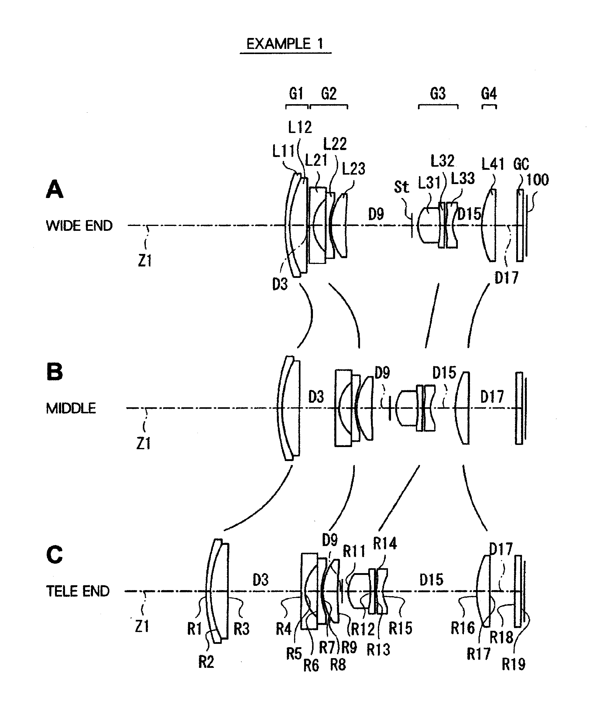
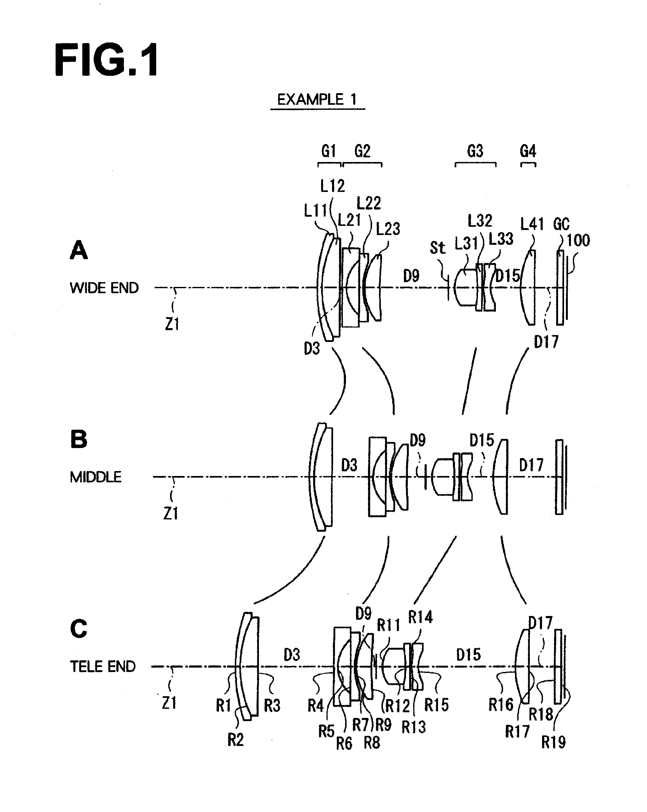
[0259][Table 1] through [Table 3] show specific lens data corresponding to the structure of the zoom lens illustrated in FIG. 1. Specifically, [Table 1] shows basic lens data, and [Table 2] and [Table 3] show other data. In the lens data of [Table 1], the column of surface number Si shows the surface number of i-th surface (i=1 through 19) of the zoom lens of Example 1, when the object-side surface of the most-object-side element is the first surface, and surface numbers sequentially increase toward the image side. The column of curvature radius Ri shows the value (mm) of the curvature radius of the i-th surface, sequentially from the object side. The curvature radius Ri in [Table 1] corresponds to sign Ri in FIG. 1. Similarly, the column of surface interval Di shows an interval (mm) between the i-th surface Si and the (i+1) th surface Si+1 on the optical axis, sequentially from the object side. The column Ndj shows the refractive index of j-th optical element from the object side f...

numerical examples 2 through 12

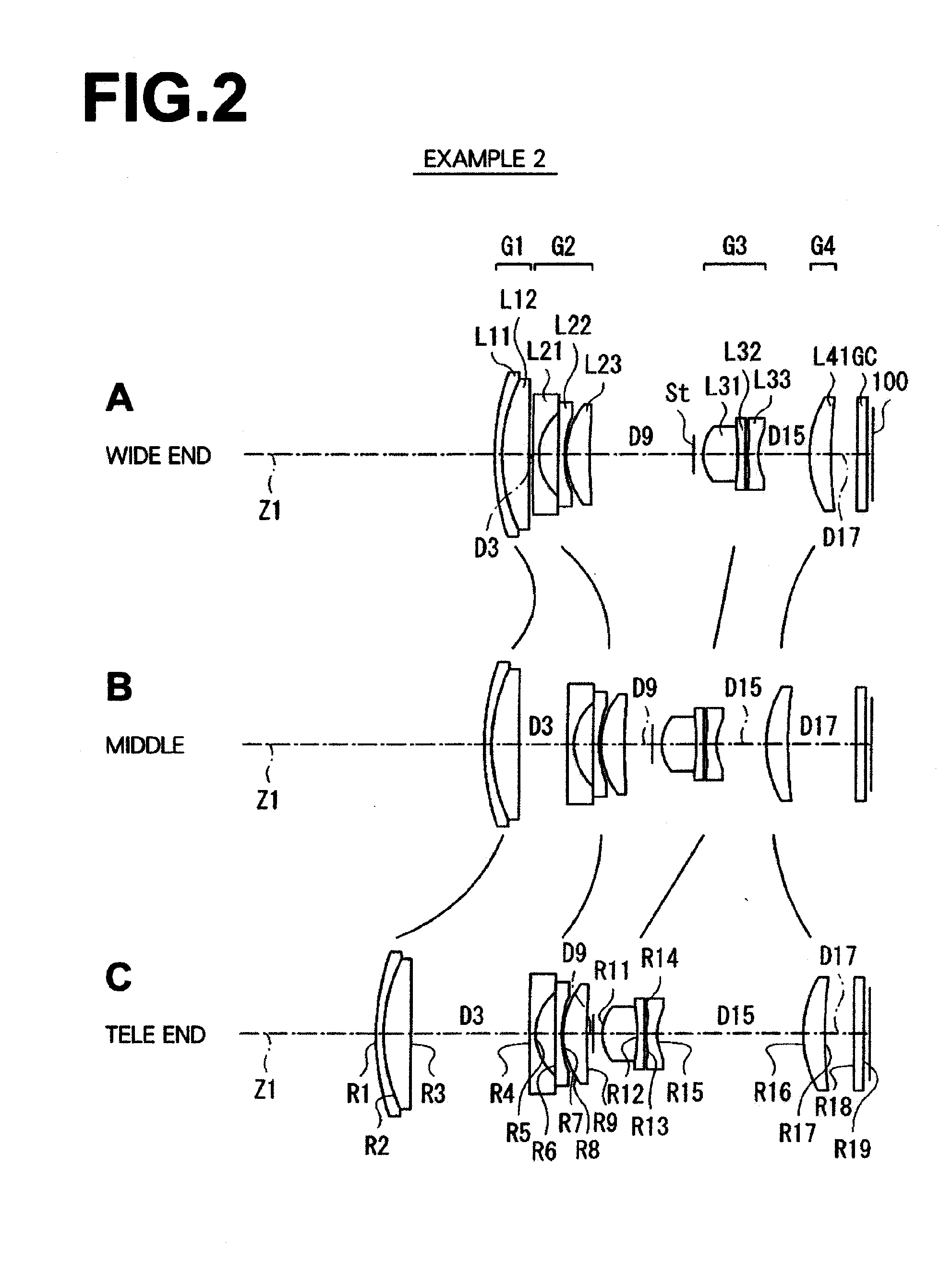
[0272][Table 4] through [Table 6] show, as Numerical Example 2, specific lens data corresponding to the structure of the zoom lens illustrated in FIG. 2 in a manner similar to Numerical Example 1. Similarly, [Table 7] through [Table 36] show, as Numerical Examples 3 through 12, specific lens data corresponding to the structure of the zoom lenses illustrated in FIGS. 3 through 12.

[0273]In the zoom lenses of Numerical Examples 2 through 8, the same surfaces as the aspheric surfaces in the zoom lens of Numerical Example 1 are aspheric. Further, aperture stop St moves together with the lens group G3.

[0274]However, in the zoom lenses of Numerical Examples 9 through 12, the number of aspheric surfaces is larger than the number of the aspheric surfaces in the zoom lens of Numerical Example 1. For example, in the zoom lens of Numerical Example 9, both sides S8, S9 of the most-image-side lens (positive lens L23) in the second lens group G2 and the image side surface S17 of the positive lens ...


PUM


Abstract

First lens-group is composed of a negative lens and a positive lens. When magnification is changed from wide end to tele end, a distance between first lens-group and second lens-group increases, and a distance between second lens-group and third lens-group decreases. Specifically, first lens-group moves toward the object side, second lens-group moves along a path convex toward the image side, third lens-group monotonously moves only toward the object side, and fourth lens-group moves along a path convex toward the object side. Further, the following formulas are satisfied:
0.3<X1/ft<0.5   (1); and
5.0<f1/fw<7.0   (2),
where X1: the amount of movement of first lens-group when magnification is changed from wide end to tele end, ft: the focal length of the entire system at tele end, f1: a combined focal length of first lens-group, and fw: the focal length of the entire system at wide end.

Description

BACKGROUND OF THE INVENTION[0001]1. Field of the Invention[0002]The present invention relates to a zoom lens appropriate for a video camera, a digital still camera, a mobile information terminal (PDA: Personal Digital Assistance), and the like, and to an imaging apparatus.[0003]2. Description of the Related Art[0004]Imaging devices, such as a CCD (Charge Coupled Device) and a CMOS (Complementary Metal Oxide Semiconductor), used in imaging apparatuses, such as a digital still camera, became small in recent years. As the size of the imaging devices decreased, a demand for reducing the size of the whole imaging apparatus increased. To reduce the size of the whole imaging apparatus, it is desirable that the entire length of the lens is short and the lens system as a whole is small. In this case, it is desirable to structure the lens, considering not only the entire length of the lens during use (photography) but also the entire length of the lens in a stored non-use state (non-photograp...

Claims


Application Information

Patent Timeline
Patent Type & Authority Applications(United States)
IPC IPC(8): H04N5/232G02B15/14
CPCG02B15/173G02B15/144113
Inventor NODA, TAIGA
Owner FUJIFILM CORP
Why Eureka
Try Eureka