

Imaging lens
a technology of image pickup and lens, applied in the field of image pickup, can solve the problems of insufficient brightness, difficult to provide all the following features, and difficulty in applying it to an increasingly thin image pickup device, etc., and achieve the effects of improving brightness, reducing aberration, and reducing the number of lenses
- Summary
- Abstract
- Description
- Claims
- Application Information
AI Technical Summary
Benefits of technology
Problems solved by technology
Method used
Image

Examples
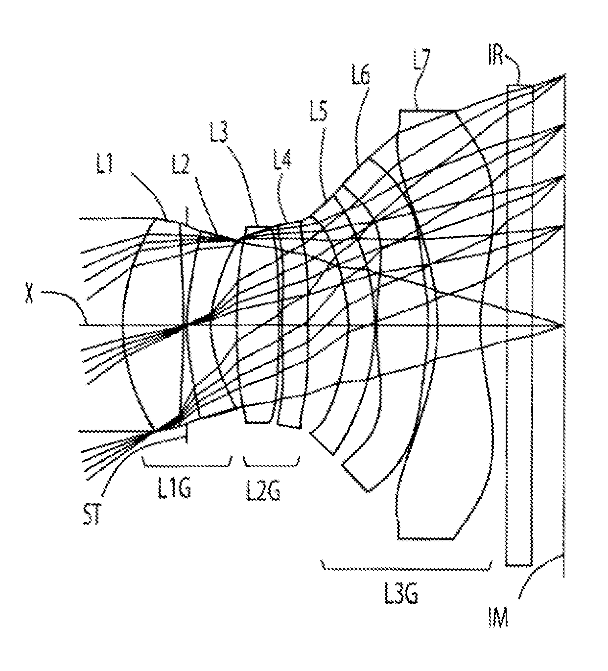
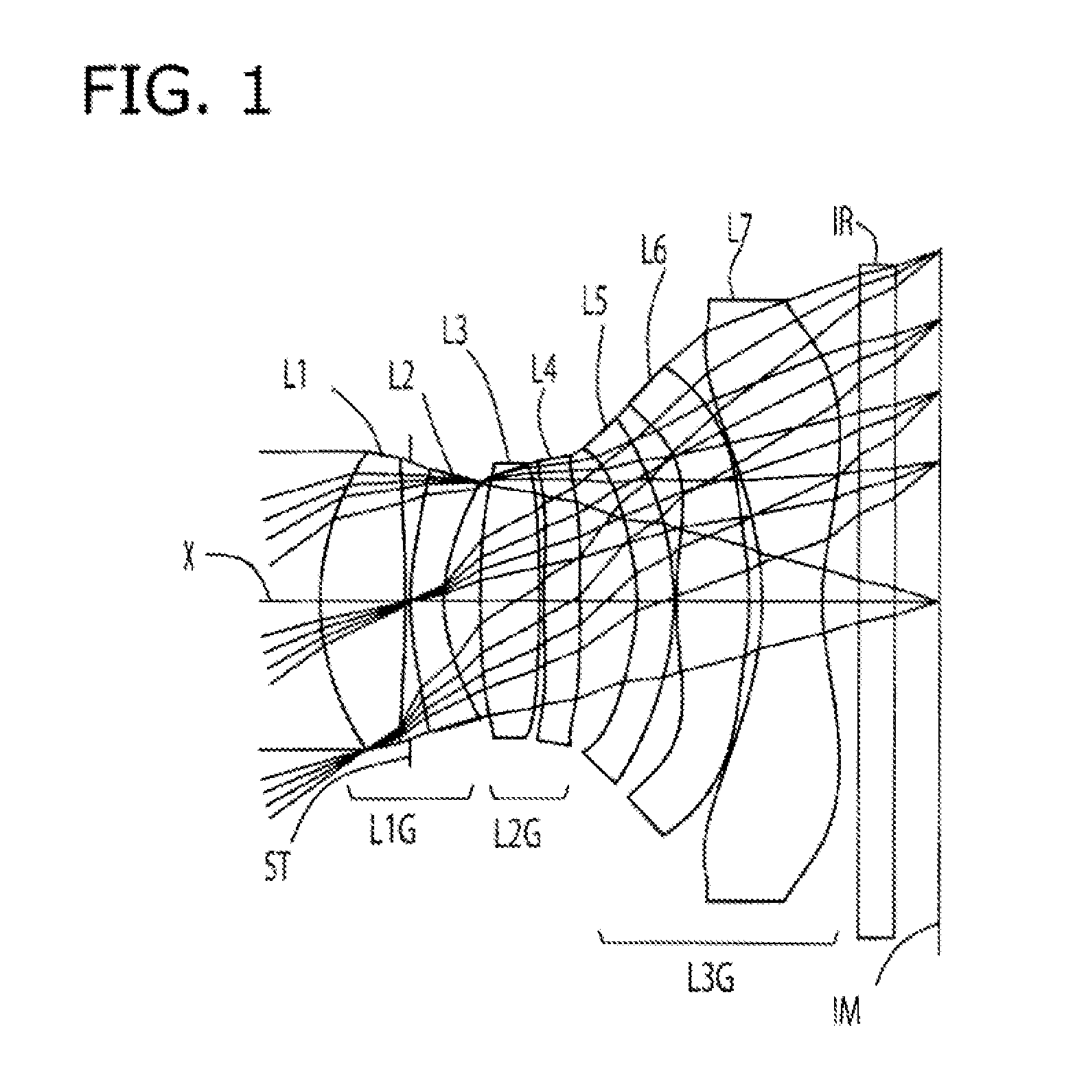
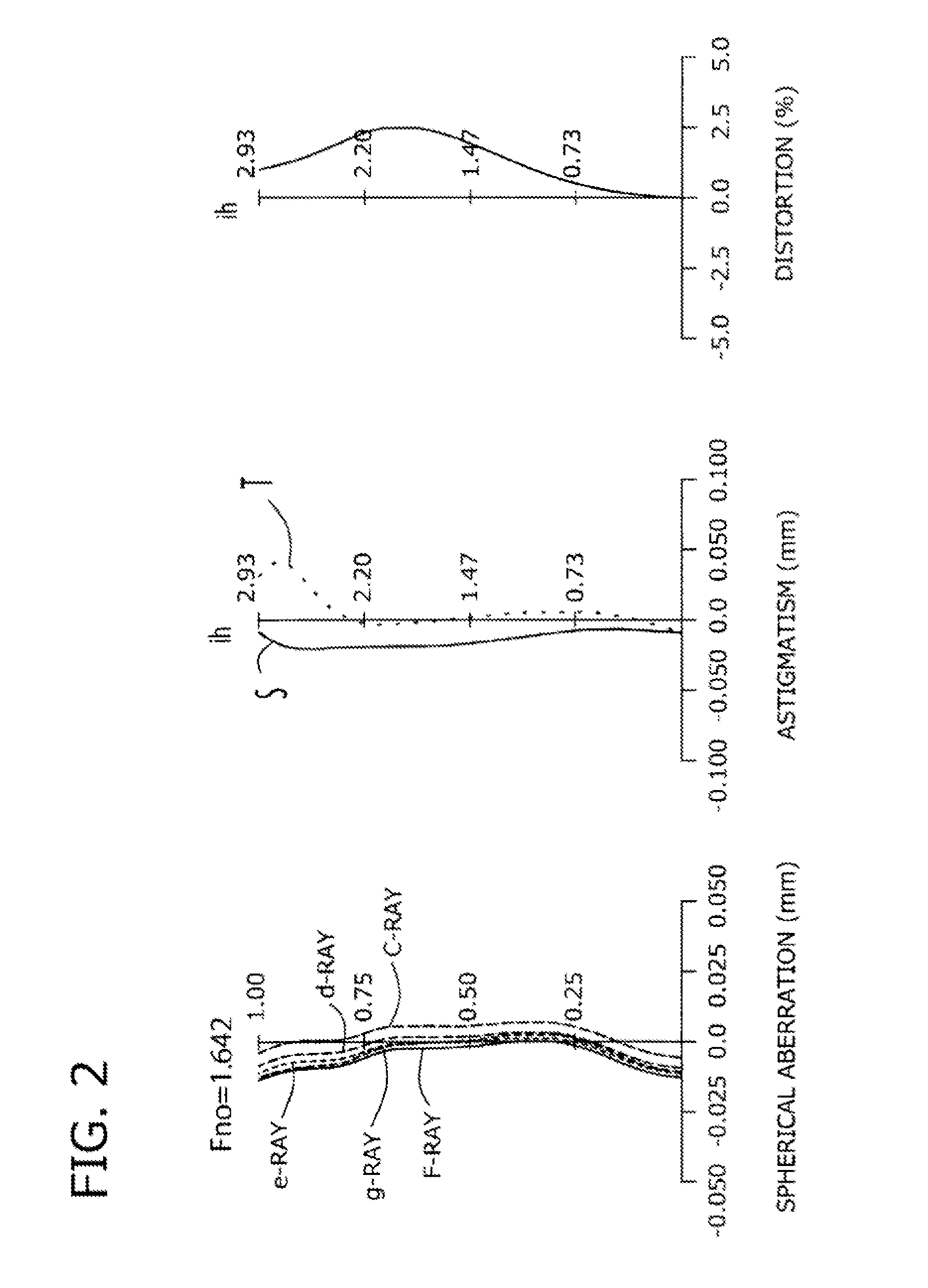
embodiment 1
[0125]The basic lens data of Embodiment 1 is shown below in Table 1.
TABLE 1Numerical Example 1in mmf = 4.06Fno = 1.64ω(deg) = 35.49ih = 2.934Surface DataCurvatureSurfaceRefractiveAbbe NumberSurface No. iRadius rDistance dIndex Ndvd(Objective Plane)InfinityInfinity 1*2.1200.7061.53556.16 2*−8.3880.045StopInfinity0.000 3*2.3280.2801.63523.91 4*1.2710.304 5*11.4990.4881.53556.16 5*−14.7780.040 7*7.1470.3001.53556.16 8*279.2330.479 9*−1.7240.3081.63523.9110*−2.4510.02511*3.2810.6031.53556.1612*−2.2760.10613*−2.7680.5001.53556.1614*1.9390.15015Infinity0.3001.51764.20Image PlaneInfinity0.517Aspheric Surface Data1st Surface2nd Surface3rd Surface4th Surface5th Surface6th Surface7th Surfacek−2.613E−010.000E+00−1.337E+01−3.683E+004.183E+010.000E+000.000E+00A43.254E−034.130E−02−9.523E−038.580E−046.036E−02−1.033E−02−9.734E−02A6−5.108E−04−1.584E−02−1.837E−021.710E−03−2.284E−02−1.354E−02−2.892E−02A8−3.395E−03−3.810E−032.118E−022.506E−022.337E−021.724E−023.955E−03A10−1.192E−034.403E−03−2.901E−03−2...
embodiment 2
[0128]The basic lens data of Embodiment 2 is shown below in Table 2.
TABLE 2Numerical Example 2in mmf = 4.05Fno = 1.64ω(deg) = 35.64ih = 2.934Surface DataCurvatureSurfaceRefractiveAbbe NumberSurface No. iRadius rDistance dIndex Ndvd(Object Plane)InfinityInfinityInfinity−0.28 1*2.22520.6871.53556.16 2*−7.4020.026 32.3500.2801.63523.91 4*1.3190.258 5*7.6910.4991.53556.16 6*38.6750.135 7*5.5970.3451.53556.16 8*−161.3340.393 9*−1.6710.3241.63523.9110*−2.3640.02511*3.2850.5971.53556.1612*−2.3810.09213*−3.2430.5001.53556.1614*1.7640.20015Infinity0.3001.51764.20Image PlaneInfinity0.491Aspheric Surface Data1st Surface2nd Surface3rd Surface4th Surface5th Surface6th Surface7th Surfacek−3.224E−010.000E+00−1.410E+01−3.794E+001.803E+010.000E+000.000E+00A43.360E−033.552E−02−9.091E−03−7.625E−035.314E−02−2.666E−02−1.118E−01A6−8.460E−03−1.679E−02−2.136E−02−7.935E−03−2.481E−02−1.773E−02−3.708E−02A84.952E−04−1.572E−032.404E−023.938E−023.264E−022.145E−02−8.888E−03A10−2.249E−031.713E−03−4.435E−03−3.624E−...
embodiment 3
[0131]The basic lens data of Embodiment 3 is shown below in Table 3.
TABLE 3Numerical Example 3in mmf = 4.07Fno = 1.64ω(deg) = 35.49ih = 2.934Surface DataCurvatureSurfaceRefractiveAbbe NumberSurface No. iRadius rDistance dIndex Ndvd(Object Plane)InfinityInfinity 1*2.27440.6841.53556.16 2*−7.1580.045StopInfinity0.000 3*2.1240.2801.63523.91 4*1.2020.290 5*12.6790.5391.53556.16 6*−3.6430.030 7*21.2130.3001.53556.16 8*9.1100.520 9*−1.7470.3001.63523.9110*−2.4760.02511*3.1080.5721.53556.1612*−2.4430.11813*−2.5820.5001.53556.1614*2.0980.15015Infinity0.3001.51764.20Image PlaneInfinity0.495Aspheric Surface Data1st Surface2nd Surface3rd Surface4th Surface5th Surface6th Surface7th Surfacek−2.650E−010.000E+00−1.004E+01−3.488E+009.900E+010.000E+000.000E+00A42.045E−035.656E−02−1.778E−02−5.991E−036.906E−021.077E−03−1.121E−01A62.534E−03−3.317E−02−3.146E−02−1.073E−02−2.159E−02−8.057E−03−4.663E−02A8−6.022E−033.803E−032.480E−021.748E−023.366E−02−1.037E−021.618E−02A106.657E−051.036E−02−1.311E−02−3.230E...
PUM
 Abstract
Description
Claims
Application Information