Valvular Closure Element, Closure Cap Comprising The Valvular Closure Element, And A Method And An Apparatus For Manufacturing The Valvular Closure Element

a technology of valvular closure and closure element, which is applied in the direction of closures, transportation and packaging, packaging, etc., can solve the problems of valve insert, large discrepancies in the operation of the closure element, and deterioration of the dispensing efficiency, so as to achieve the effect of convenient and effective assembly

Active Publication Date: 2016-10-27
FAZEKAS GABOR
View PDF8 Cites 4 Cited by
  • Summary
  • Abstract
  • Description
  • Claims
  • Application Information

AI Technical Summary

Benefits of technology

[0009]A yet further object of the invention is to provide a valvular closure element which allows to avoid the deterioration of the valve insert before its insertion into a cap as much as possible.
[0011]A further object of the invention is to provide a valvular closure element which can be handled and assembled easier and more effective than the known valvular closure elements.

Problems solved by technology

A common disadvantage of the above described known solutions is that the valve insert has to be rotationally positioned before inserting into the cap, i.e. the sides of the valve insert and the cap have to be exactly parallel.
Even a small error in the positioning may lead to large discrepancies in the operation of the closure cap.
For example, an error in the rotational positioning can deteriorate the dispensing efficiency thereof.
Another disadvantage of the known solutions is that the valve insert and the receiving cap are produced separately.
Therefore, a large quantity of valve inserts has to be packed in the same package, and these products have to be built into the cap of the partner manufacturer elsewhere.
These soft articles can get damaged during the transportation, and the valve inserts have to be positioned one by one in another factory.
A further disadvantage of the known solutions is that the cap receiving the valve insert—the product of another factory—needs a very special configuration, i.e. the projections of pressing ribs in its internal periphery.

Method used


Image

  • Valvular Closure Element, Closure Cap Comprising The Valvular Closure Element, And A Method And An Apparatus For Manufacturing The Valvular Closure Element
  • Valvular Closure Element, Closure Cap Comprising The Valvular Closure Element, And A Method And An Apparatus For Manufacturing The Valvular Closure Element
  • Valvular Closure Element, Closure Cap Comprising The Valvular Closure Element, And A Method And An Apparatus For Manufacturing The Valvular Closure Element

Examples


Embodiment Construction

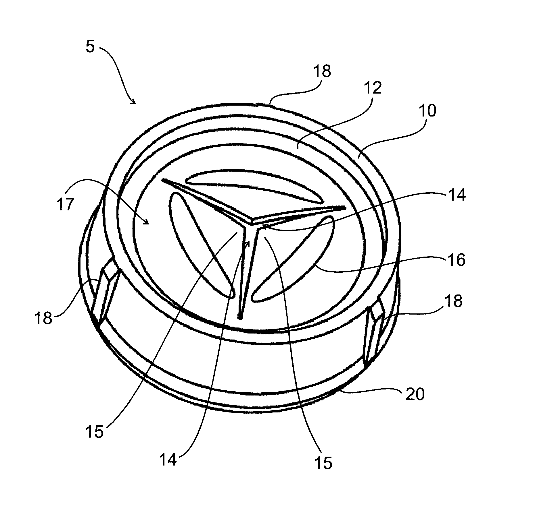
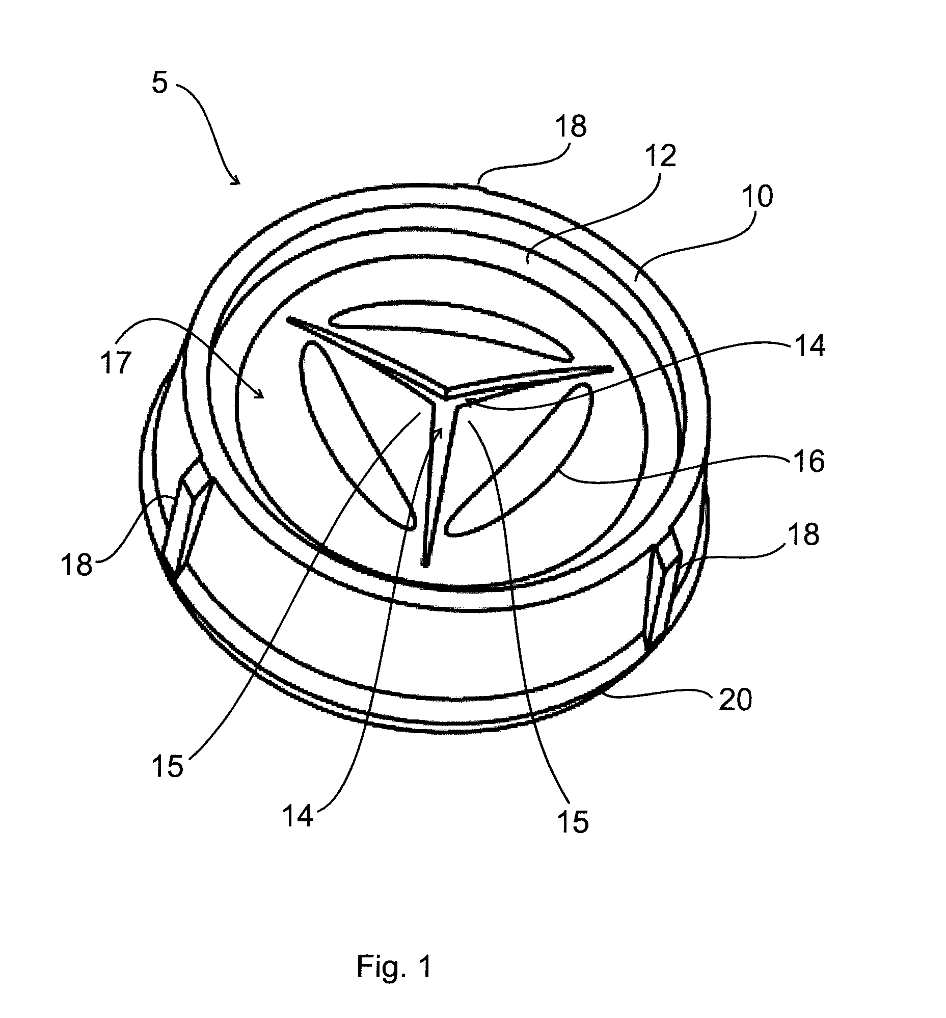
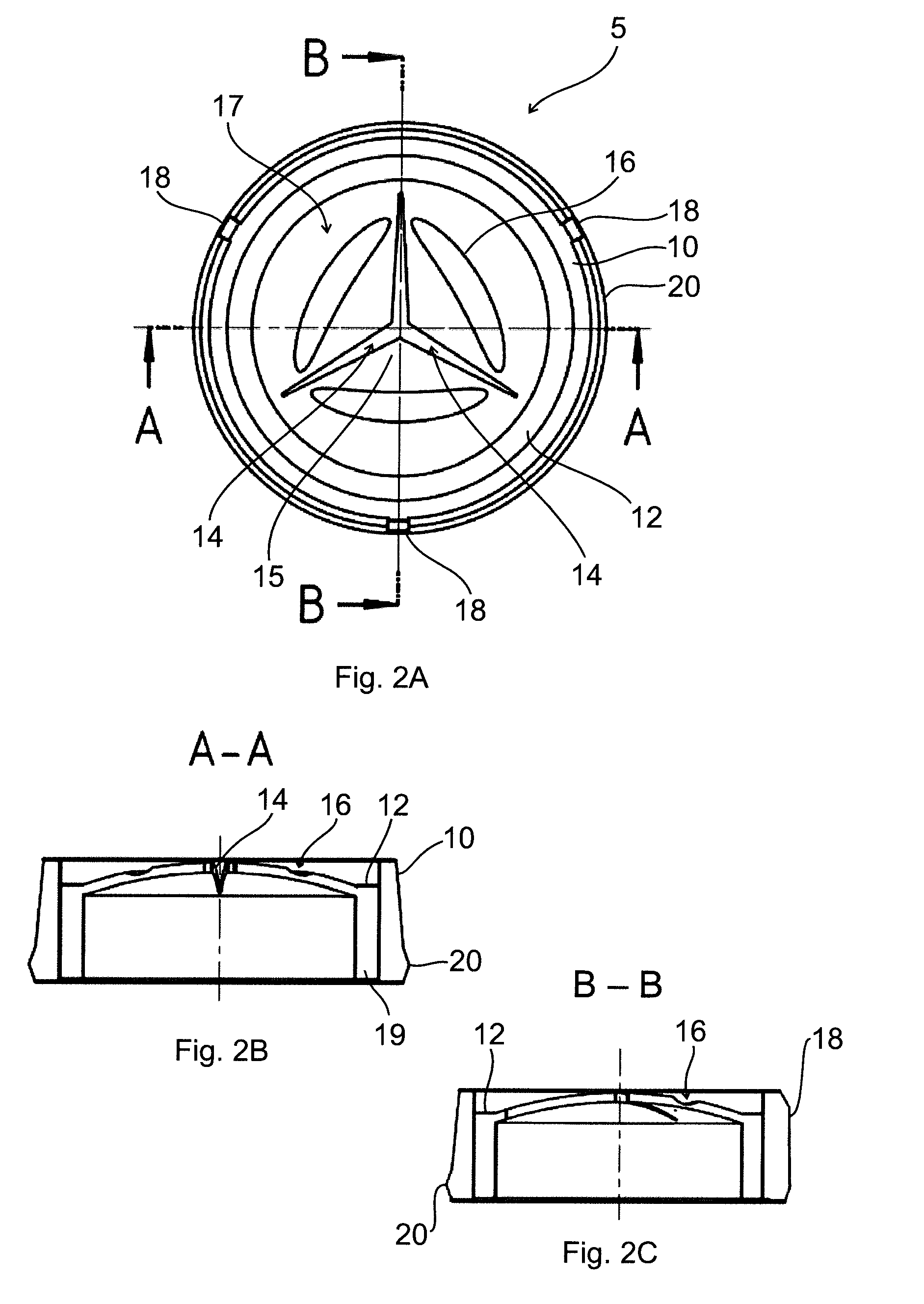
[0077]In FIG. 1 an embodiment of the valvular closure element according to the invention is shown. The valvular closure element according to the invention is adapted in particular for dispensing liquid from a container. The valvular closure element 5 comprises a support element 10 having an annular shape, and a valve insert 12 having a side wall 19 (see FIG. 3B) and a cover portion 17. The side wall 19 and the cover portion 17 are shown e.g. in FIG. 3B. The valve insert 12 is made of a resilient material, is abutting to an internal surface of the support element 10 by its side wall 19. The cover portion 17 is formed with slits 14 defining valve flaps 15. Each valve flap 15 has an adjoining periphery connected to the side wall 19. The adjoining periphery extends preferably along an arched line at the connection of a valve flap 15 to the side wall 19, but of course, an adjoining periphery with a polygon shape is also conceivable.

[0078]In the valvular closure element 5 the side wall 19...


PUM

PropertyMeasurementUnit
heightaaaaaaaaaa
radial heightaaaaaaaaaa
cylindrical shapeaaaaaaaaaa

Abstract

The invention is a valvular closure element (5), in particular for dispensing a liquid from a container, the valvular closure element (5) comprising a support element (10) having an annular shape and a valve insert (12) having a side wall and a cover portion made of a resilient material and abutting to an internal surface of the support element (10) by its side wall. The cover portion (17) is formed with slits (14) defining valve flaps (15), wherein each valve flap (15) has an adjoining periphery connected to the side wall. In the valvular closure element (5) the side wall has a cylindrical shape, and the slits (14) are formed radially, and a projection (18) is formed on the external periphery of the support element (10) for each valve flap (15) at the middle of the adjoining periphery corresponding to the respective valve flap (15). The invention is, furthermore, a closure cap comprising the valvular closure element (5), and a method and an apparatus for manufacturing the valvular closure element (5). The invention also relates to another valvular closure element.

Description

TECHNICAL FIELD[0001]The invention relates to a valvular closure element comprising a valve insert and a support element encompassing the valve insert. The invention also relates to a closure cap comprising the valvular closure element and a method and an apparatus for manufacturing the valvular closure element. The invention further relates to a valvular closure element comprising a valve insert and a receiving element, and to a closure cap comprising thereof. The valvular closure element is in particular adapted for dispensing liquids (e.g. ketchup, mustard, mayonnaise, shampoo, liquid soap, hair conditioner, etc.) from a container.BACKGROUND ART[0002]In HU 227 230 B1 a closure cap provided with a valve and adapted for dispensing liquid from a storage container is disclosed. According to the document, a valve insert made of a resilient material is produced by injection moulding with opened valve flaps. The valve insert has a triangle like side wall, i.e. the side wall has an equiv...

Claims


Application Information

Patent Timeline
Patent Type & Authority Applications(United States)
IPC IPC(8): B65D47/20B29C45/40B29C45/00
CPCB65D47/2031B29C45/0003B29K2023/10B29K2023/04B29C45/4005
Inventor RIDEG, MIHALY
Owner FAZEKAS GABOR
Why Eureka
Try Eureka