Method and Criteria for Trajectory Control
a trajectory control and trajectory technology, applied in the direction of electric controllers, surveyors, borehole/well accessories, etc., can solve the problem that the actual wellbore trajectory deviates from the design well path
- Summary
- Abstract
- Description
- Claims
- Application Information
AI Technical Summary
Benefits of technology
Problems solved by technology
Method used
Image
Examples
example one
[0092]A computer-implemented method for performing automated downhole wellbore trajectory control for correcting between an actual wellbore trajectory path and a planned wellbore trajectory path, the method comprising: receiving real-time path data for determining the actual wellbore trajectory path; receiving parameters for the planned wellbore trajectory path; determining whether the actual wellbore trajectory path deviates from the planned wellbore trajectory path; responsive to a determination that the actual wellbore trajectory path deviates from the planned wellbore trajectory path, determining whether the actual wellbore trajectory path deviates from a correction path; responsive to a determination that the actual wellbore trajectory path deviates from the correction path; determining a target point along the planned wellbore trajectory path for modifying the correction path; determining trajectory correction parameters using a minimum incremental wellbore energy method; and ...
example two
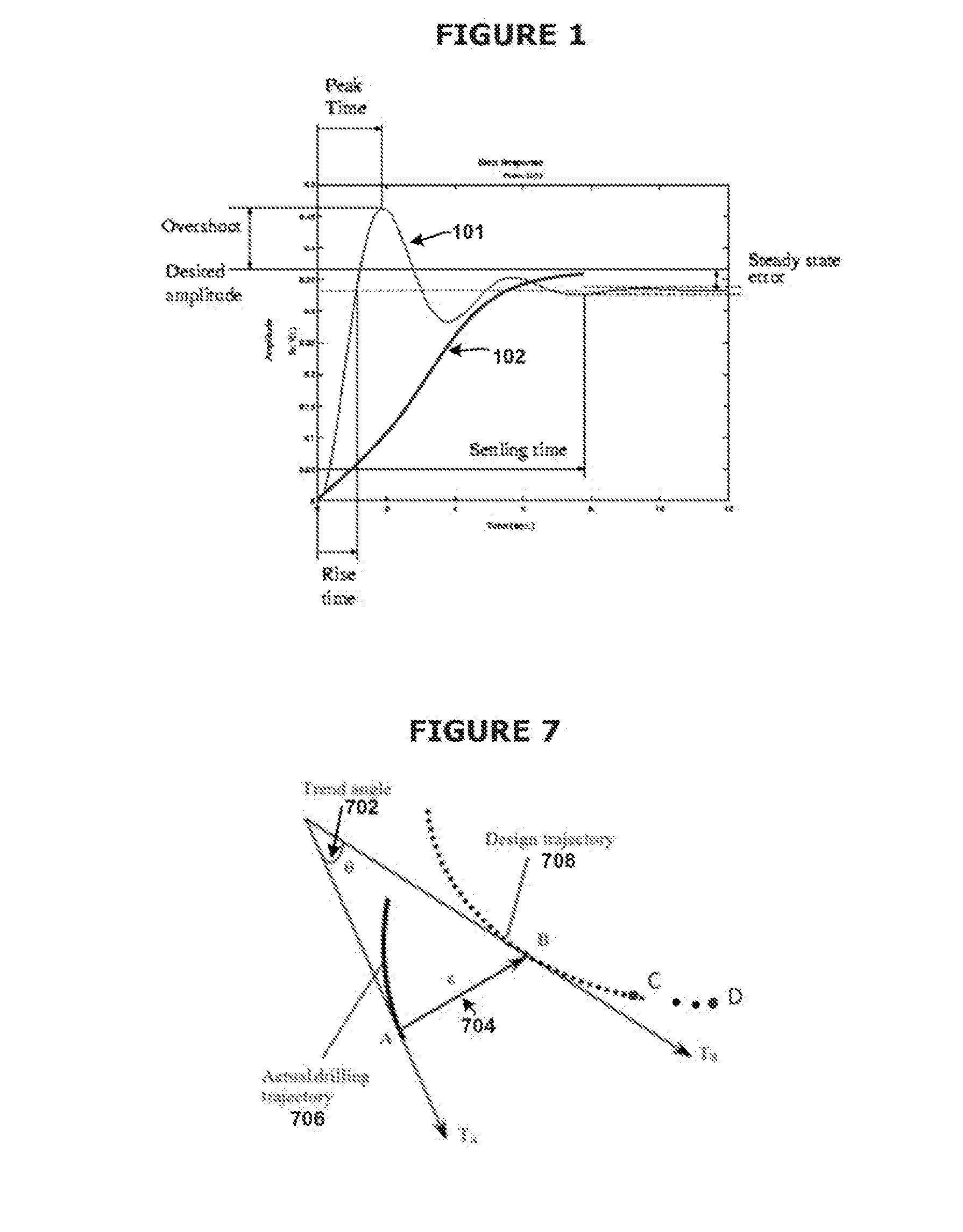
[0093]A computer-implemented method for performing automated downhole wellbore trajectory control for correcting between an actual wellbore trajectory path and a planned wellbore trajectory path, the method comprising: receiving real-time path data for determining the actual wellbore trajectory path; receiving parameters for the planned wellbore trajectory path; determining a trend angle and a deviation vector length between the actual wellbore trajectory path and the planned wellbore trajectory path; determining whether the actual wellbore trajectory path deviates from the planned wellbore trajectory path; responsive to a determination that the actual wellbore trajectory path deviates from the planned wellbore trajectory path, determining whether the actual wellbore trajectory path deviates from a correction path; responsive to a determination that the actual wellbore trajectory path deviates from the correction path; determining a target point along the planned wellbore trajectory...
example three
[0094]A computer-implemented method for performing automated downhole wellbore trajectory control for correcting between an actual wellbore trajectory path and a planned wellbore trajectory path, the method comprising: receiving real-time path data for determining the actual wellbore trajectory path; receiving parameters for the planned wellbore trajectory path; determining whether the actual wellbore trajectory path deviates from the planned wellbore trajectory path; responsive to a determination that the actual wellbore trajectory path deviates from the planned wellbore trajectory path, determining whether the actual wellbore trajectory path deviates from a correction path; responsive to a determination that the actual wellbore trajectory path deviates from the correction path; determining a target point along the planned wellbore trajectory path for modifying the correction path; determining trajectory correction parameters using a minimum incremental wellbore energy method; dete...
PUM
 Abstract
Description
Claims
Application Information
 - R&D
- Intellectual Property
- Life Sciences
- Materials
- Tech Scout
- Unparalleled Data Quality
- Higher Quality Content
- 60% Fewer Hallucinations
Browse by: Latest US Patents, China's latest patents, Technical Efficacy Thesaurus, Application Domain, Technology Topic, Popular Technical Reports.
© 2025 PatSnap. All rights reserved.Legal|Privacy policy|Modern Slavery Act Transparency Statement|Sitemap|About US| Contact US: help@patsnap.com


