Bearing equipped with an axial displacement detecting device

a detection device and bearing technology, applied in the field of bearings, can solve the problems of bearing parts, which cooperate to transmit loads, wear, displacement of rings relative, and the risk of bearing rings or parts of frame elements coming into contact with each other

Active Publication Date: 2016-10-27
AB SKF
View PDF8 Cites 12 Cited by
  • Summary
  • Abstract
  • Description
  • Claims
  • Application Information

AI Technical Summary

Benefits of technology

The technical effect of this patent is to provide an improved design for controlling the position of an object or person by measuring their movement through a sensor. This involves placing the control unit in a specific location on the device carrying the ring, allowing for more accurate measurements.

Problems solved by technology

The technical problem addressed by this patent is how to prevent damage to bearings caused by excessive load and reduce the cost associated with replacing them at an incorrect time.

Method used


Image

  • Bearing equipped with an axial displacement detecting device
  • Bearing equipped with an axial displacement detecting device
  • Bearing equipped with an axial displacement detecting device

Examples


Embodiment Construction

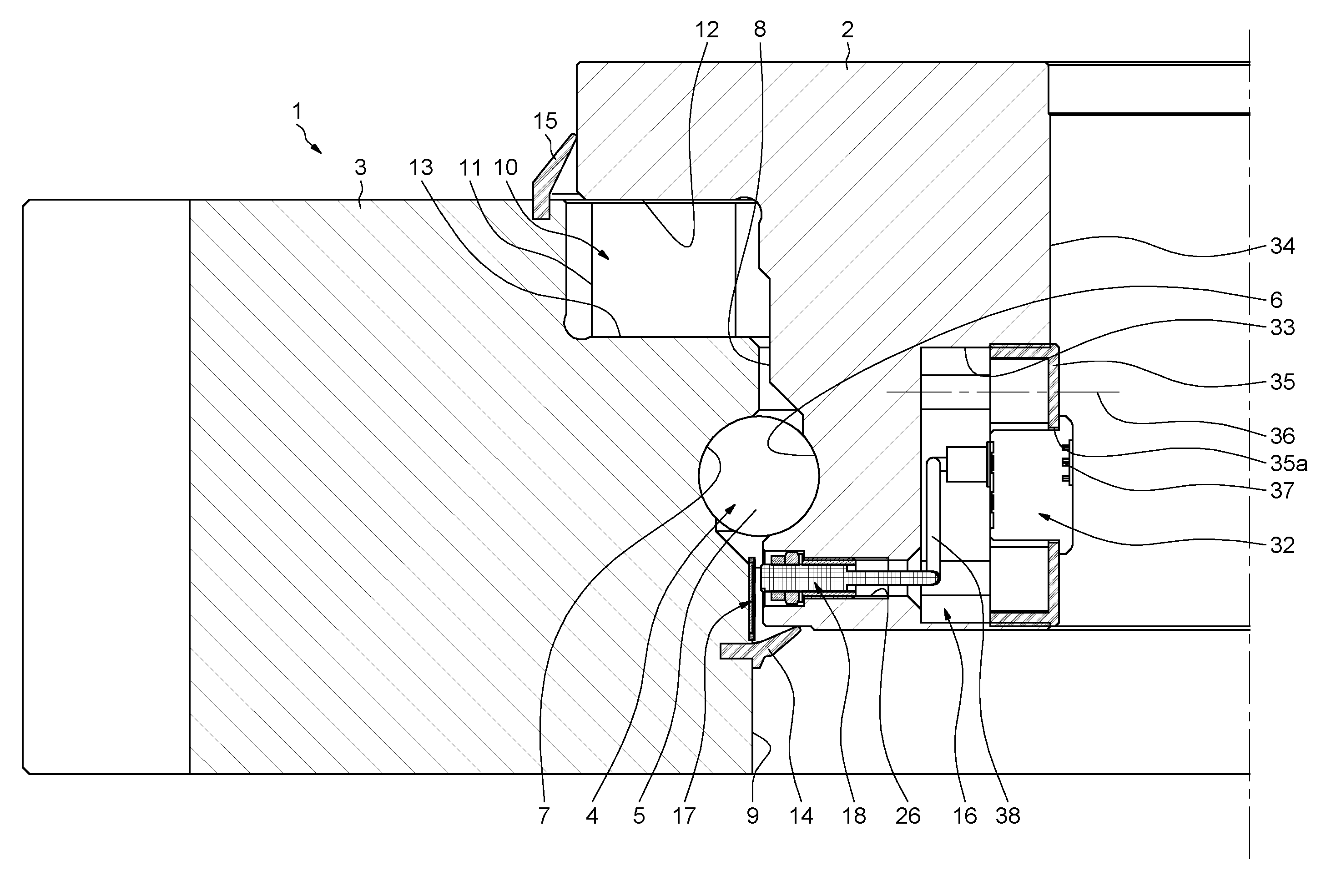
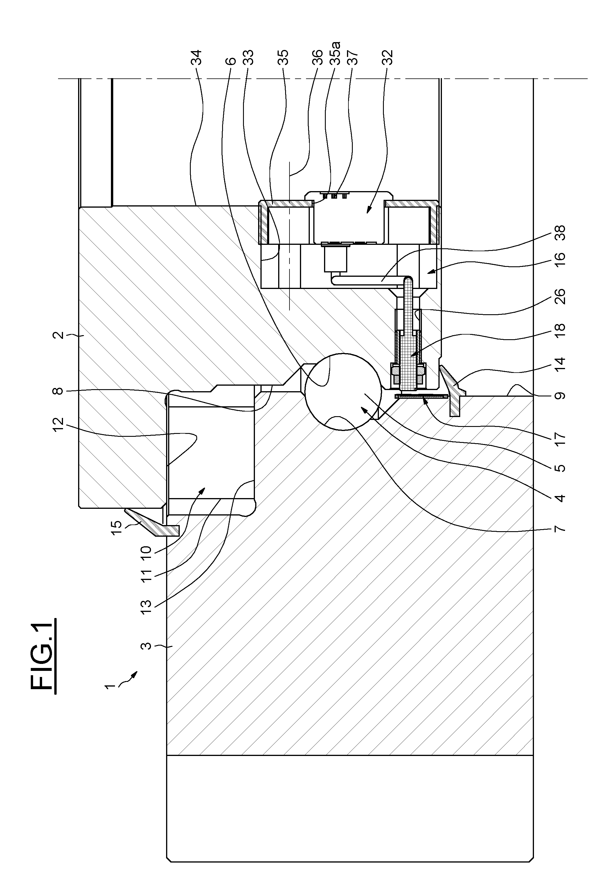
[0020]As illustrated in FIG. 1, a rolling element bearing 1 provides an inner ring 2 and an outer ring 3 concentrically disposed about an axis of rotation (not shown) which will be considered by way of example as being in a vertical position. The bearing rings 2 and 3 are intended to be fixed on respective frame elements (not shown) to permit rotation of one frame element relative to the other and transmit loads therebetween.

[0021]For supporting radial loads, the rolling element bearing 1 includes, for example, a row 4 of rolling elements 5, such as balls, rolling on opposing annular raceways 6 and 7 provided as grooves in the respective cylindrical faces 8 and 9 of the inner ring 2 and the outer ring 3.

[0022]For supporting the axial loads, the rolling element bearing 1 includes, for example, a row 10 of rolling elements 11, such as rollers, rolling on opposing axially oriented raceways 12 and 13 of the inner ring 2 and the outer ring 3 respectively. The axially oriented raceway 12 ...


PUM


Abstract

A bearing providing at least an inner ring and an outer ring adapted to concentrically rotate with respect to one another, equipped with at least one embedded device for the detection of a displacement in translation of the rings relative to each other, the detection device including a linear encoder element mounted on one of the rings, and a sensor element mounted on the other ring and opposite the encoder element.

Description


Claims


Application Information

Patent Timeline
Owner AB SKF
Why Eureka
Try Eureka