
Ceiling-embedded air conditioner

Active Publication Date: 2016-10-27
FUJITSU GENERAL LTD
View PDF5 Cites 6 Cited by
  • Summary
  • Abstract
  • Description
  • Claims
  • Application Information

AI Technical Summary

Benefits of technology

The present air conditioner stops air from flowing directly onto a human sensor, which helps prevent malfunctions in the sensor.

Problems solved by technology

This easily causes uneven room temperatures.

Method used


Image

  • Ceiling-embedded air conditioner
  • Ceiling-embedded air conditioner
  • Ceiling-embedded air conditioner

Examples


Embodiment Construction

[0018]In the following detailed description, for purpose of explanation, numerous specific details are set forth in order to provide a thorough understanding of the disclosed embodiments. It will be apparent, however, that one or more embodiments may be practiced without these specific details. In other instances, well-known structures and devices are schematically shown in order to simplify the drawing.

[0019]The human sensor is generally a pyroelectric infrared sensor. If the human sensor described in JP-A-2011-257112 is applied as one of energy-saving measures to the omnidirectional ceiling-embedded air conditioner described in JP No. 4052264, there are causes for concerns as described below.

[0020]Specifically, in the omnidirectional ceiling-embedded air conditioner, the conditioned air also flows into the corner portions of the decorative panel. Accordingly, the conditioned air strikes directly the human sensor at the corner portion. When the hot or cool air strikes directly the ...


PUM


Abstract

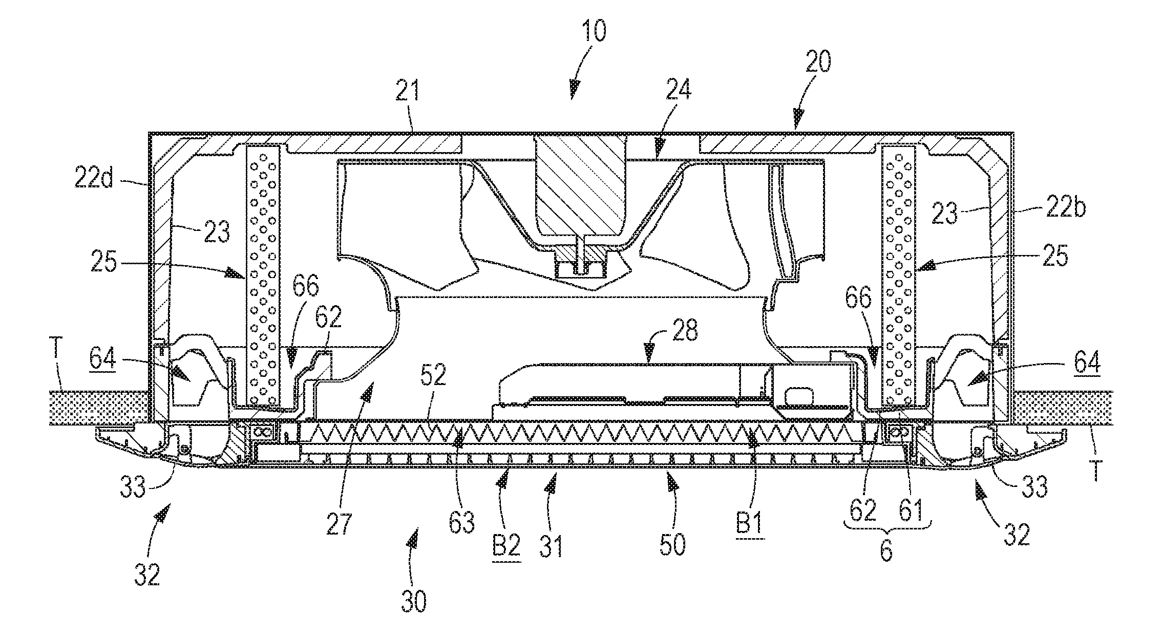
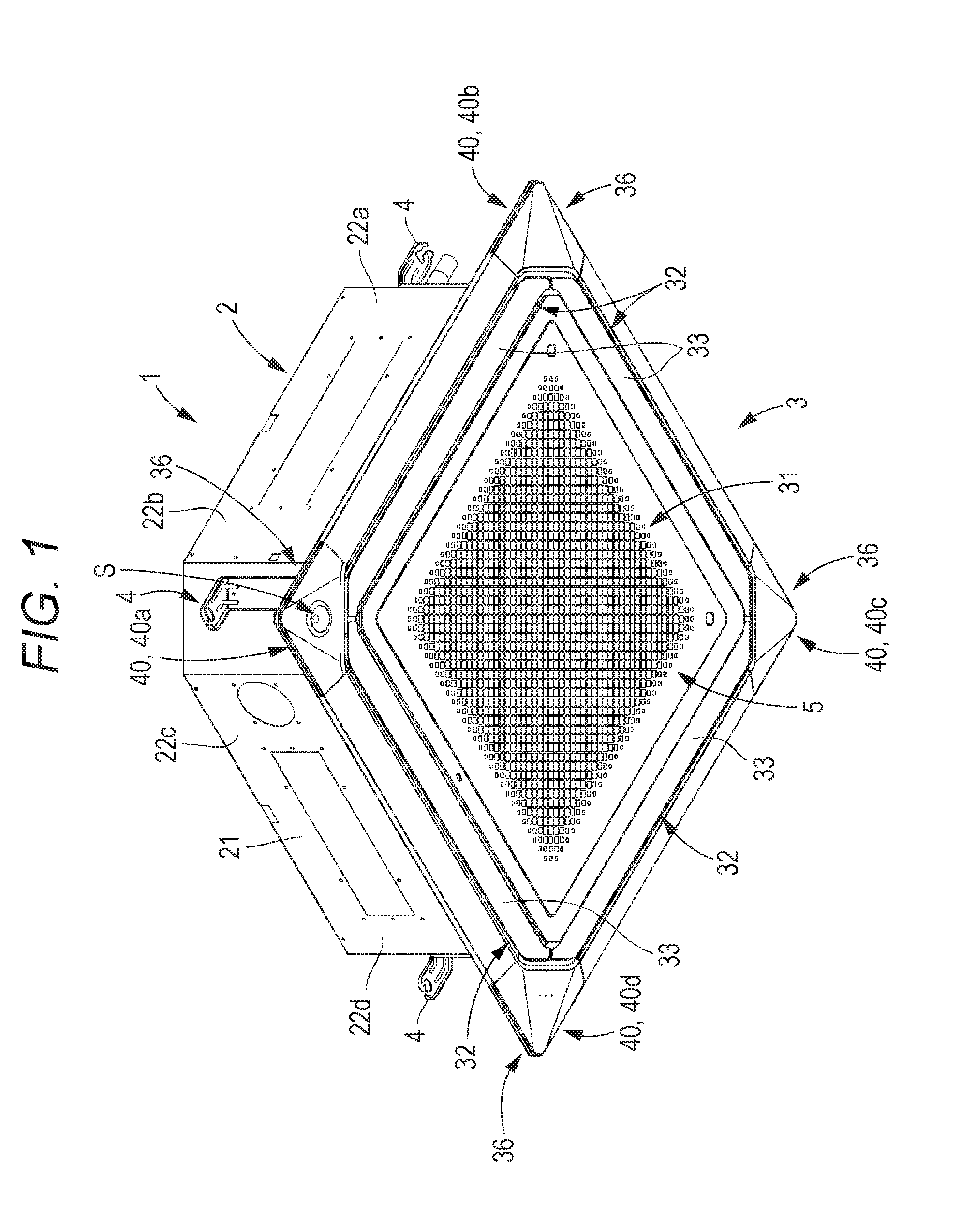
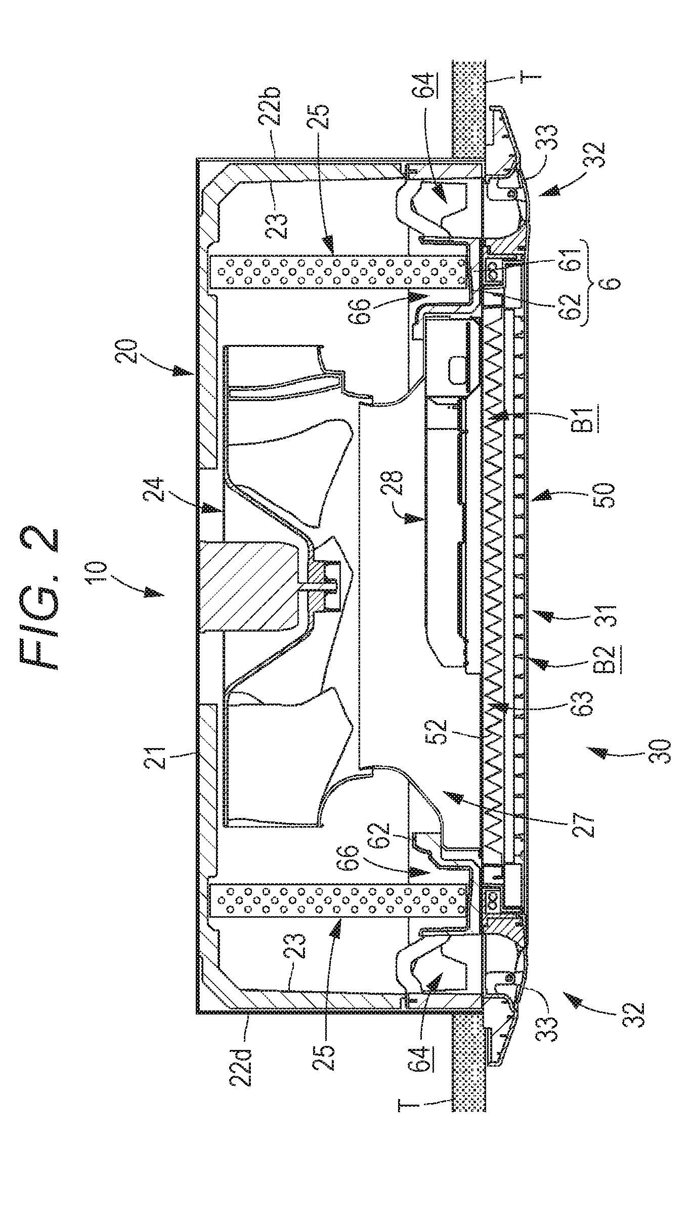
A ceiling-embedded air conditioner includes: a decorative panel; a turbo fan; a heat exchanger; an air suction path; air blowoff paths; an air suction opening and air blowoff openings that are provided in the decorative panel; corner panels disposed at corner portions between the adjacent air blowoff openings; a human sensor that is provided on a specific corner panel; a wind guide path that flows conditioned air blown from the air blowoff openings; and windbreak ribs that are erected from the specific corner panel to suppress direct strike, on the human sensor, of the conditioned air flowing from the wind guide path to the specific corner panel.

Description

CROSS-REFERENCE TO RELATED APPLICATION[0001]This application claims priority from Japanese Patent Application No. 2015-090274 filed with the Japan Patent Office on Apr. 27, 2015, the entire content of which is hereby incorporated by reference.BACKGROUND[0002]1. Technical Field[0003]The present disclosure relates to a ceiling-embedded air conditioner that is embedded in a space between a ceiling slab and a ceiling panel. More specifically, the present disclosure relates to a ceiling-embedded air conditioner that has a blowoff structure blowing conditioned air from air blowoff openings toward all directions.[0004]2. Description of the Related Art[0005]In a ceiling-embedded air conditioner, a box-shaped casing main body is embedded in a space formed between a ceiling slab and a ceiling panel. A square decorative panel is mounted on the lower surface (facing the interior of a room) of the casing main body. In general, an air suction opening is provided in the center of the decorative pa...

Claims


Application Information

Patent Timeline
IPC IPC(8): F24F11/00F24F13/30F24F13/14F24F13/22F24F11/02F24F1/00F24F13/20
CPCF24F11/0034F24F1/0022F24F13/30F24F13/20F24F1/0014F24F2011/0035F24F11/02F24F11/0078F24F13/14F24F2001/0037F24F13/22F24F2120/10F24F11/30F24F1/0047F24F1/0007F24F13/08F24F11/79F24F2013/0616F24F2120/12F01P11/10F24F11/89
Inventor NAKAMURA, YUTA
Owner FUJITSU GENERAL LTD
Learn More