Interferometric measurement method for guide holes and fiber holes parallelism and position in multi-fiber ferrules
- Summary
- Abstract
- Description
- Claims
- Application Information
AI Technical Summary
Benefits of technology
Problems solved by technology
Method used
Image

Examples
Embodiment Construction
[0035]Reference will now be made in detail to the presented measurement method illustrated in the accompanying drawings.
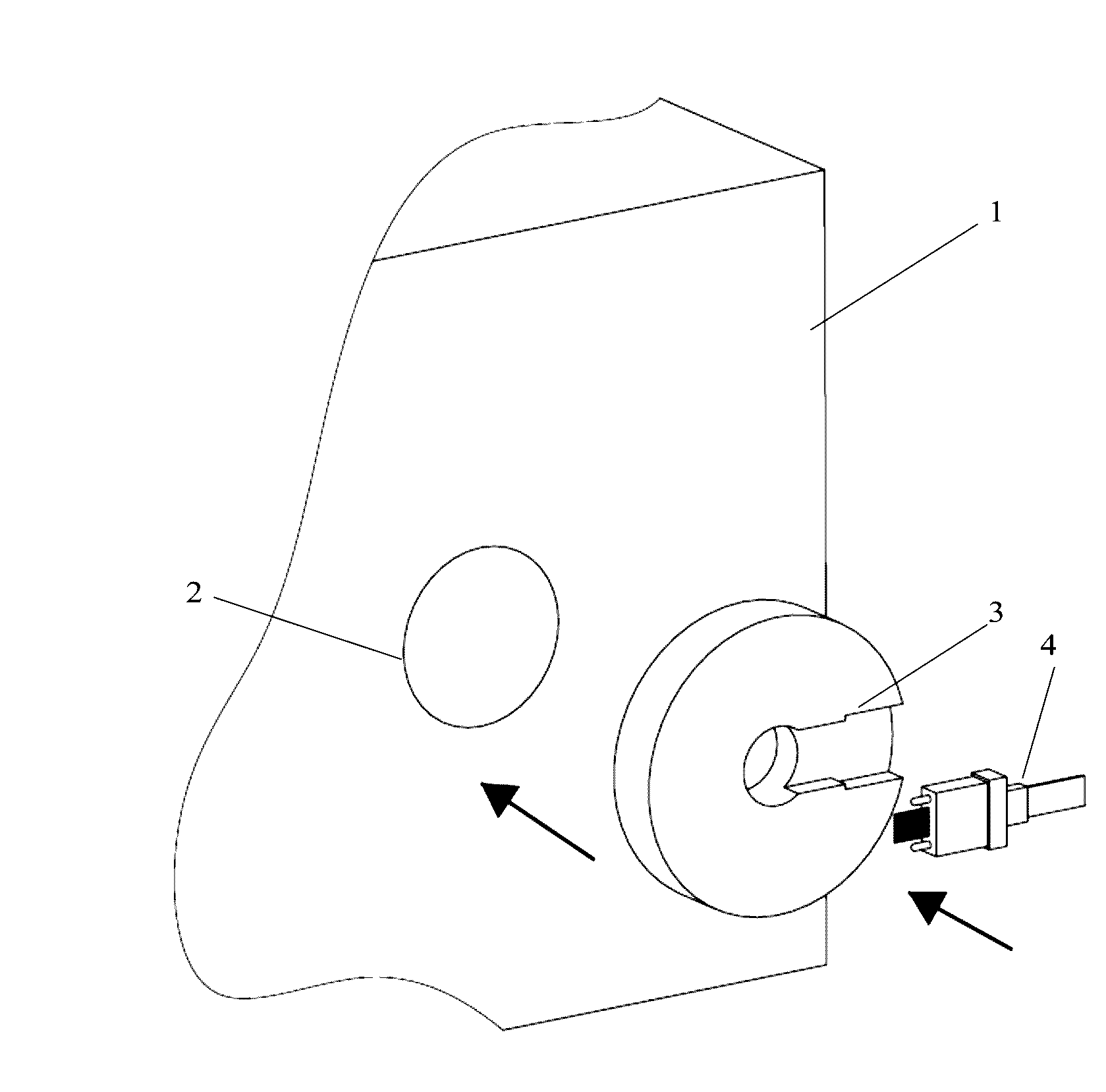
[0036]FIG. 1 illustrates an exemplary embodiment of the present invention. The reference number 1 represents an interferometric microscope. A special fixture 3 for side measurements of multi-fiber ferrules is mounted on the microscope which has an opening 2 to receive the fixture. A multi-fiber ferrule 4 is inserted into the fixture for side face measurements. The ferrule contains first and second reference guide pins and a reference fiber ribbon inserted into the ferrule as explained by FIG. 2.
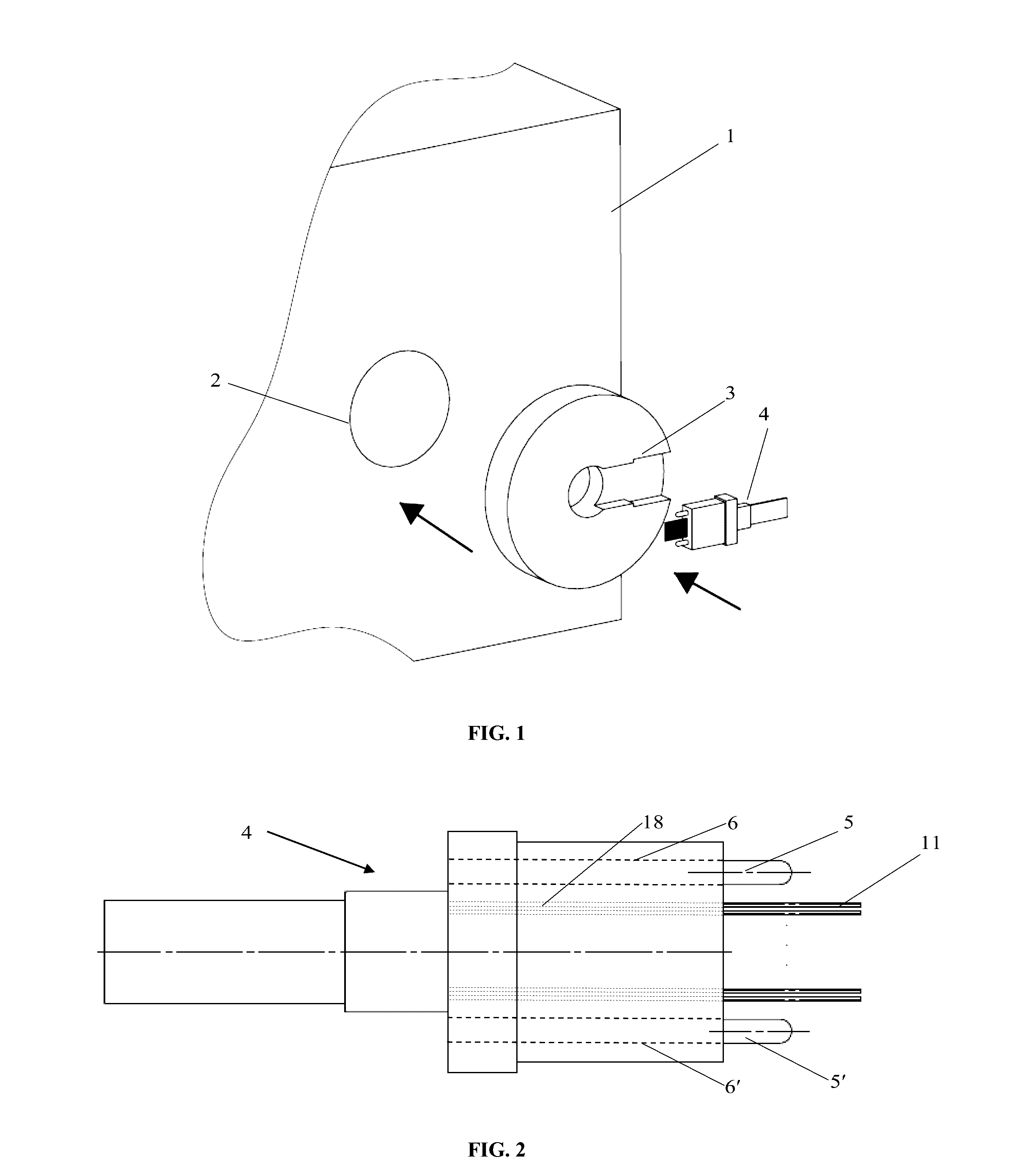
[0037]FIG. 2 shows a top view of a multi-fiber ferrule 4 in a state ready for testing. In original state, the multi-fiber ferrule has first and second guide holes 6 and 6′ in which first and second alignment guide pins 5 and 5′ are inserted. The multi-fiber ferrule 4 also has a number of fiber holes 18, depending on the type of a multi-fiber connector being manufactured. The...
PUM
 Abstract
Description
Claims
Application Information
 - R&D
- Intellectual Property
- Life Sciences
- Materials
- Tech Scout
- Unparalleled Data Quality
- Higher Quality Content
- 60% Fewer Hallucinations
Browse by: Latest US Patents, China's latest patents, Technical Efficacy Thesaurus, Application Domain, Technology Topic, Popular Technical Reports.
© 2025 PatSnap. All rights reserved.Legal|Privacy policy|Modern Slavery Act Transparency Statement|Sitemap|About US| Contact US: help@patsnap.com