
Method for inverse tone mapping of an image

a technology of image and tone, applied in the field of high dynamic range imaging, can solve the problems of not addressing existing content, unable to offer sufficient control over the appearance of images, and still very limited hdr content available, and achieve the effect of increasing the dynamic range and enhancing the hdr appearance of conten

Active Publication Date: 2016-11-10
INTERDIGITAL MADISON PATENT HLDG SAS
View PDF0 Cites 21 Cited by
  • Summary
  • Abstract
  • Description
  • Claims
  • Application Information

AI Technical Summary

Benefits of technology

The patent describes a method for enhancing the appearance of high dynamic range (HDR) content on display devices with limited dynamic range. The method extracts high frequency luminance values from the spatial neighborhood of each pixel to increase its luminance. This enhancement compensates for the smoothing of image details caused by low pass filtering of luminance values. The method adapts to both the content and the luminance range of the display device, allowing for a more HDR appearance even with modest increases in dynamic range.

Problems solved by technology

Although a number of HDR display devices have appeared, and image cameras capable of capturing images with an increased dynamic range are being developed, there is still very limited HDR content available.
While recent developments promise native capture of HDR content in the near future, they do not address existing content.
In the simplest case, clipped regions in the image can be detected and then expanded using a steeper expansion curve, however such a solution does not offer sufficient control over the appearance of the image.

Method used


Image

  • Method for inverse tone mapping of an image
  • Method for inverse tone mapping of an image
  • Method for inverse tone mapping of an image

Examples


first embodiment

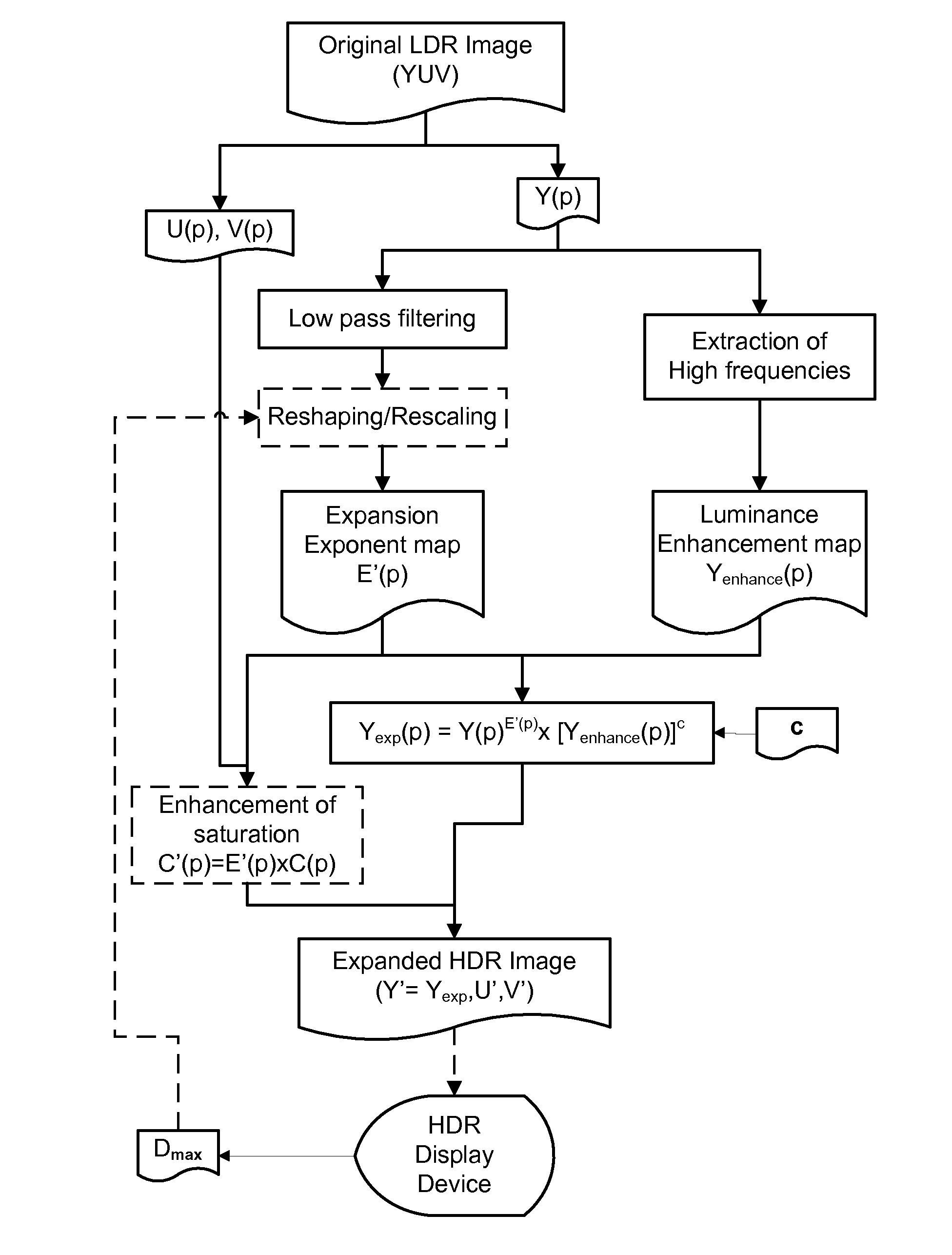
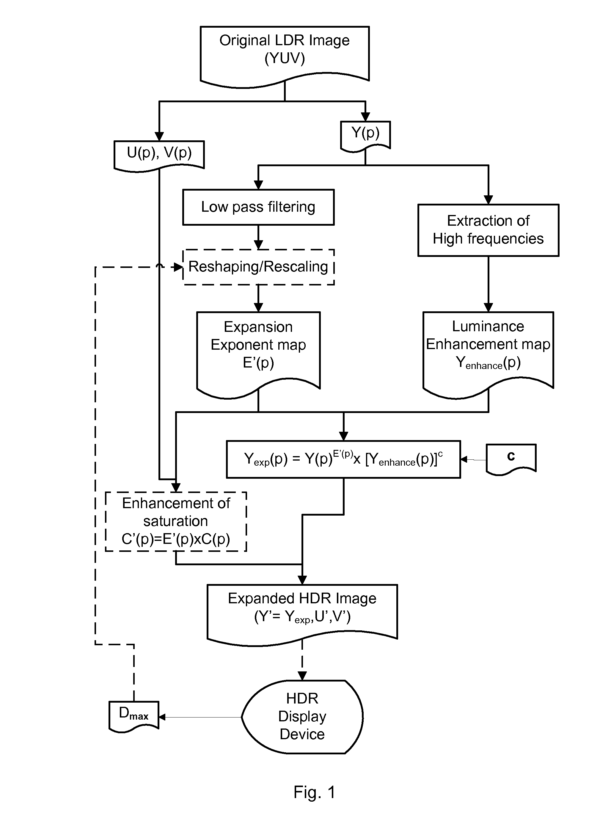
[0052]the method for the inverse tone mapping of an image will now be described in reference to FIG. 1, using the image processing device as described above.

[0053]Using for instance an image receiver, an image is received with all data related to colors of each pixel, wherein the color associated with each pixel of this image is encoded into three color coordinates, i.e. one color coordinate for each color channel, R, G and B.

[0054]In a first preparation step of this embodiment (not shown on FIG. 1), the received RGB color coordinates of these colors are, if needed, normalized and optionnaly linearized in a manner known per se, such that the colors of the received image are represented in the RGB color space of a display device. This RGB color space can be standardized, and the corresponding display device is a virtual one. Then, these colors are converted to a color space separating luminance from chrominance, for instance the YUV color space. This conversion of colors from the RGB...

second embodiment

[0112]the method for the inverse tone mapping of an image will now be disclosed, using an image processing device as described above, but configured specifically to implement this embodiment.

[0113]When compared to the first embodiment, the only differences concern:

[0114]the second step of obtaining, for each pixel p, a pixel expansion exponent value E(p) by low pass filtering the luminance values of pixels in a spatial neighborhood of the pixel p,

[0115]the fourth step of extracting high spatial frequencies to obtain a pixel luminance-enhancement value Yenhance(p) for each pixel p of the image.

[0116]In this second embodiment, the colors are received as sets of three color coordinates representing these colors in a color space separating luminance from chrominance, for instance the YUV color space. Again, any other color space separating luminance from chrominance can be used instead. Therefore, a luminance value Y(p) and two chrominance values U(p), V(p) are associated to the color o...


PUM


Abstract

Method comprising, for each pixel, obtaining a pixel expansion exponent value (E′(p)) by low pass filtering luminance values of colors of pixels in its spatial neighborhood, obtaining a pixel luminance-enhancement value (Yenhance(p)) by extraction of high frequencies of luminance values of colors of pixels in its spatial neighborhood, and then inverse tone mapping the luminance (Y(p)) according to the equation Yexp(p)=Y(p)E′(p)×[Yenhance(p)]c.

Description

TECHNICAL FIELD[0001]The invention pertains to the field of high dynamic range imaging and addresses notably the problem of expanding the dynamic range of low dynamic range content to prepare such content for display devices having notably high peak luminance.BACKGROUND ART[0002]Recent advancements in display technology are beginning to allow for an extended range of color, luminance and contrast to be displayed.[0003]Technologies allowing for extensions in luminance or brightness range of image content are known as high dynamic range imaging, often shortened to HDR. HDR technologies focus on capturing, processing and displaying content of a wider dynamic range.[0004]Although a number of HDR display devices have appeared, and image cameras capable of capturing images with an increased dynamic range are being developed, there is still very limited HDR content available. While recent developments promise native capture of HDR content in the near future, they do not address existing co...

Claims


Application Information

Patent Timeline
IPC IPC(8): G06T5/00G06K9/46G06K9/52G06T7/40
CPCG06T5/007G06T7/408G06K9/4661G06T2207/20024G06T2207/20064G06T2207/20208G06K9/52H04N5/57H04N21/4318G06T7/90H04N23/741G06T5/94G06T5/90
Inventor POULI, TANIAREINHARD, ERIKCHAMARET, CHRISTEL
Owner INTERDIGITAL MADISON PATENT HLDG SAS
Learn More