System and Method for a Driving a Radio Frequency Switch

a radio frequency switch and system technology, applied in the field of electronic devices, can solve the problems of degrading an rf signal, large voltage swing, and voltage swings that may exceed the breakdown voltag

Active Publication Date: 2016-11-10
INFINEON TECH AG
View PDF5 Cites 51 Cited by
  • Summary
  • Abstract
  • Description
  • Claims
  • Application Information

AI Technical Summary

Benefits of technology

[0004]In accordance with an embodiment, a radio frequency (RF) switching circuit includes a plurality of series connected RF switch cells comprising a load path and a control node, a plurality of first gate resistors coupled between control nodes of adjacent RF switch cells, and an input resistor having a first end coupled to a control node of one of the plurality of RF switch cells and a second end configured to an output of a switch driver. Each of the plurality of series connected RF switch cells includes a switch transistor.

Problems solved by technology

As RF components are becoming more integrated in fine geometry integrated circuit processes, there are number of technical challenges with respect to fabricating RF switches that have good high frequency performance.
One such challenge is handling large voltage swings that may occur during the course of a signal transmission.
In some cases, these voltage swings may exceed the breakdown voltages of the particular semiconductor process technology being used.
Another challenge to integrating RF switches involves managing the parasitic environment of the RF switch itself, as large devices used to withstand higher voltages may be prone to higher parasitic capacitances that may attenuate and / or degrade an RF signal.

Method used


Image

  • System and Method for a Driving a Radio Frequency Switch
  • System and Method for a Driving a Radio Frequency Switch
  • System and Method for a Driving a Radio Frequency Switch

Examples


Embodiment Construction

[0013]The making and using of the presently preferred embodiments are discussed in detail below. It should be appreciated, however, that the present invention provides many applicable inventive concepts that can be embodied in a wide variety of specific contexts. The specific embodiments discussed are merely illustrative of specific ways to make and use the invention, and do not limit the scope of the invention.

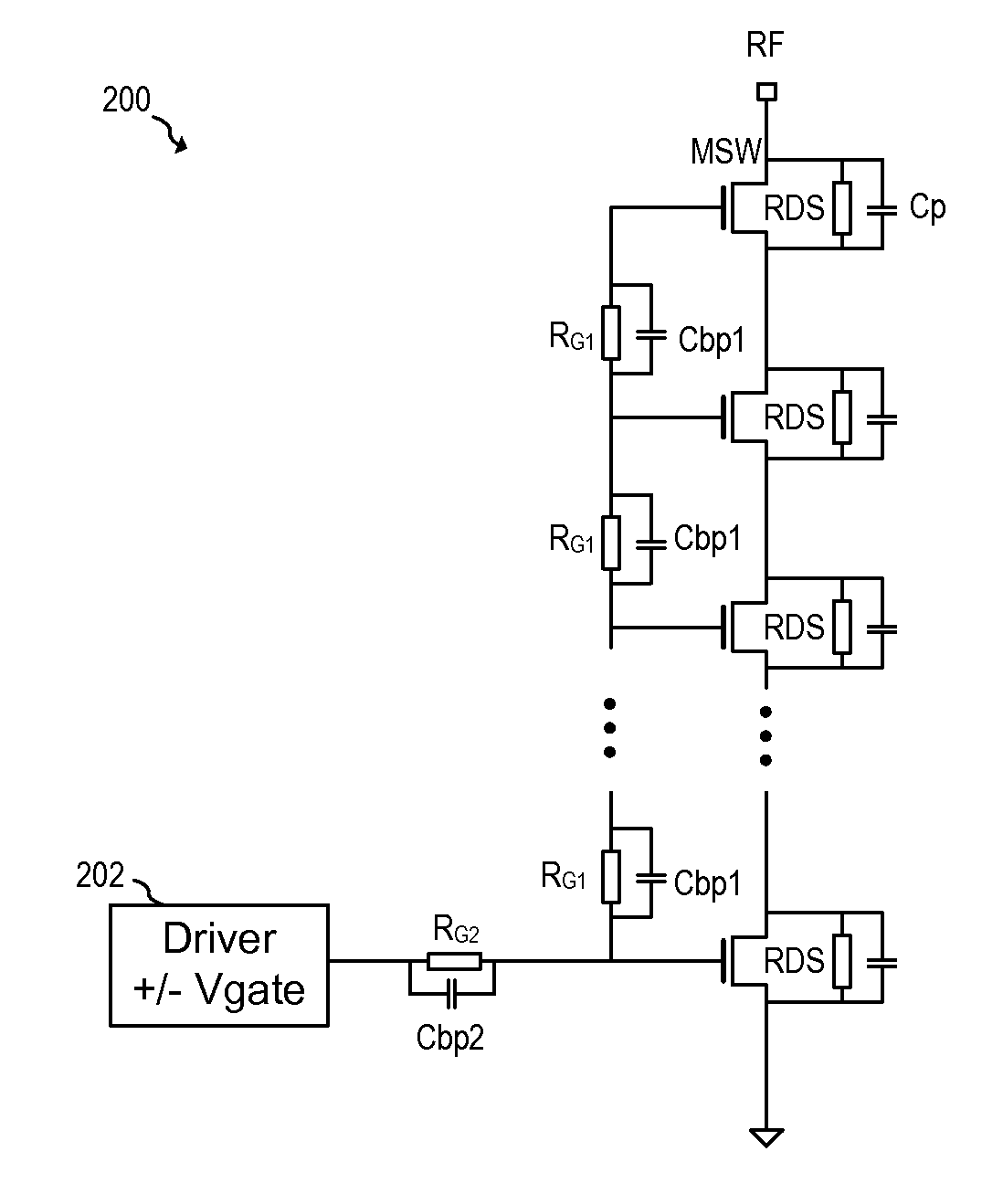
[0014]The present invention will be described with respect to preferred embodiments in a specific context: a system and method for driving a radio frequency (RF) switch. The invention may also be applied to other systems and applications including other circuits that utilize switches for high frequency applications such as wireless and wireline communication systems, radar systems, and in circuits such as oscillators, receive / transmit switches, attenuators, power amplifier bypass circuits, RF matching and RF filter switching in general.

[0015]In embodiments of the present inve...


PUM


Abstract

In accordance with an embodiment, a radio frequency (RF) switching circuit includes a plurality of series connected RF switch cells comprising a load path and a control node, a plurality of first gate resistors coupled between control nodes of adjacent RF switch cells, and an input resistor having a first end coupled to a control node of one of the plurality of RF switch cells and a second end configured to an output of a switch driver. Each of the plurality of series connected RF switch cells includes a switch transistor.

Description

TECHNICAL FIELD[0001]The present disclosure relates generally to an electronic device, and more particularly to a system and method for driving a radio frequency (RF) switch.BACKGROUND[0002]RF switches are used in a variety of RF circuits to implement various functions. For instance, an RF system using different signaling methods over different frequencies may be implemented by using a network of antenna switches to select from between different types of RF front-end circuits. One example of such a circuit is a multi-standard cellular telephone that can make calls using different standards such as code division multiple access (CDMA) or Global System for Mobile Communications (GSM). By using an RF switch, an RF front end circuit optimized for CDMA communication may be used for CDMA calls, while and RF front end circuit optimized for GSM communication may be used for GSM calls. In addition, RF switches may be used to implement adjustable matching networks for antennas and power ampli...

Claims


Application Information

Patent Timeline
Patent Type & Authority Applications(United States)
IPC IPC(8): H03K17/687
CPCH03K17/6874H03K17/693H03K17/6871H04B1/44
Inventor BAKALSKI, WINFRIEDSTELTENPOHL, ANTONTADDIKEN, HANS
Owner INFINEON TECH AG
Why Eureka
Try Eureka