Rotating electric machine stator

Active Publication Date: 2016-11-17
TOYOTA JIDOSHA KK +1
View PDF3 Cites 4 Cited by
  • Summary
  • Abstract
  • Description
  • Claims
  • Application Information

AI Technical Summary

Benefits of technology

The present invention provides a rotating electric machine stator that improves coil insertability while ensuring good insulation performance. The stator has insulators with multiple surfaces that prevent interference between the coil and insulator when slots are narrow. The insulators' inner peripheral surfaces only touch the first surfaces, and the insulating performance is not adversely affected by the second surfaces. This allows for better coil insertability while maintaining good insulation.

Problems solved by technology

In this case, when concentrated winding coils are used in an integrated stator, the coil that is to be installed last must be deformed before it is installed as described in JP 2008-220093 A. At this time, when stepped insulators are used, the corner portions of the deformed coil may interfere with the steps of the insulator.
Thus, because the coil must be installed carefully in order to avoid the interference, the coil insertability is poor.
When the width of the teeth is reduced in order to improve the coil insertability, the space factor of the coils decreases, which can cause a decrease in performance of the rotating electric machine or other problems.

Method used


Image

  • Rotating electric machine stator
  • Rotating electric machine stator
  • Rotating electric machine stator

Examples


Embodiment Construction

[0026]An embodiment of the present invention is described below in detail with reference to the drawings. The dimensions, shapes, materials and so on that are described below are shown for illustrative purposes and may be changed as needed depending on the design of the rotating electric machine stator and so on. In addition, in the following, the same elements are designated in all the drawings by the same reference numerals and redundant description is not repeated.

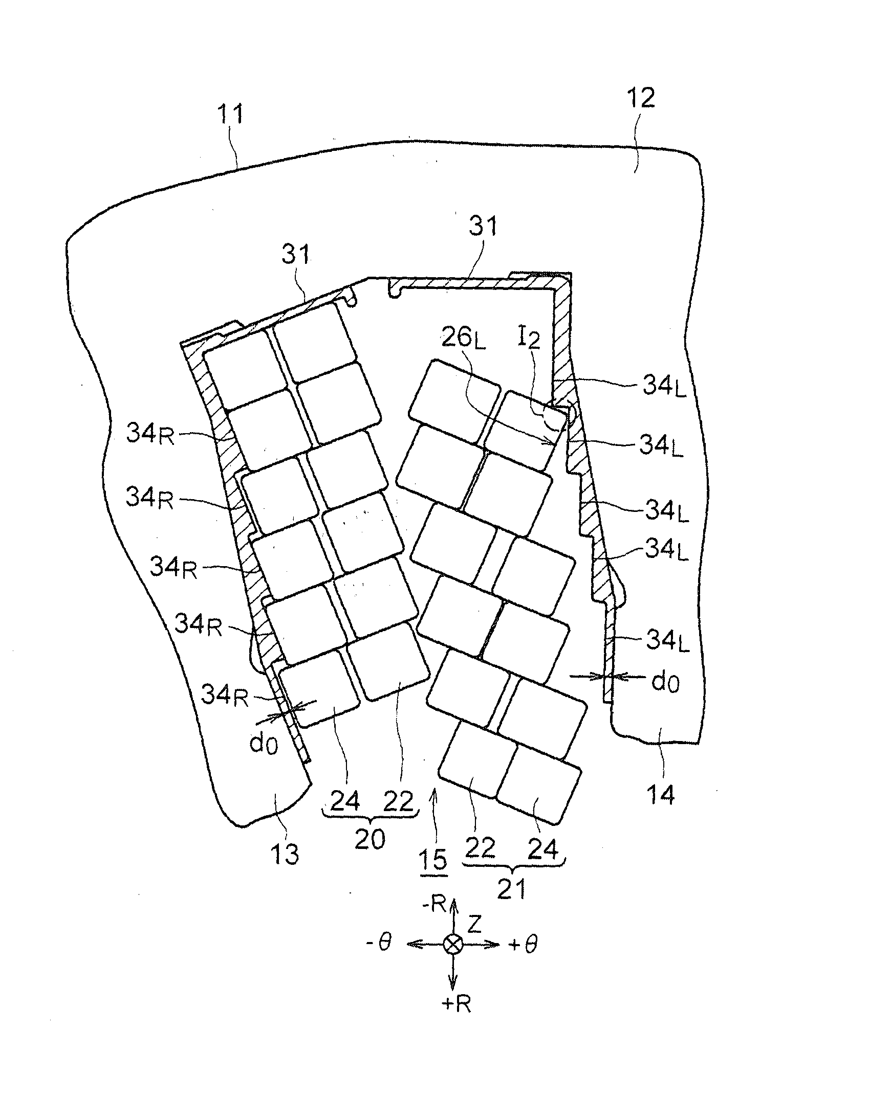
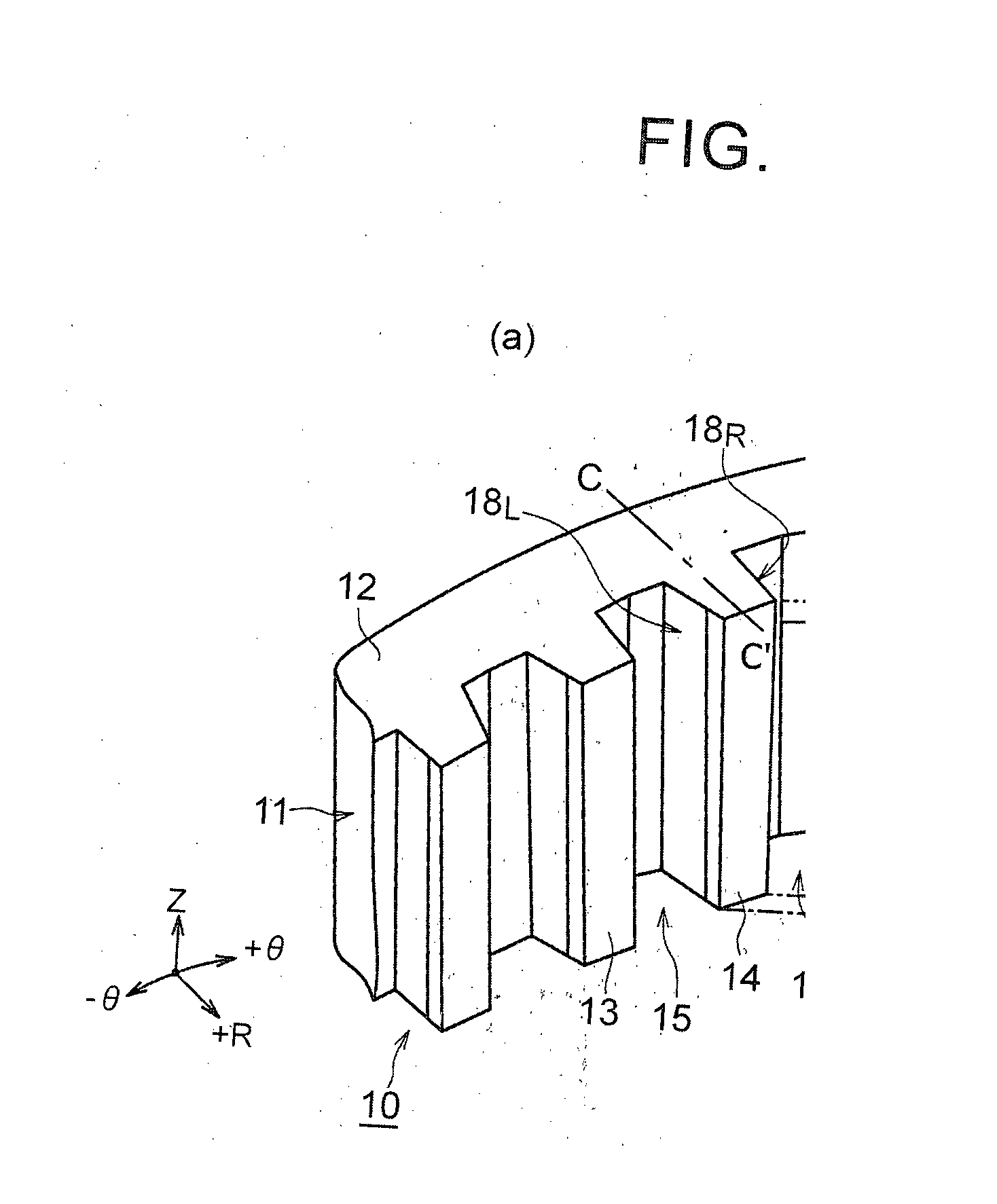
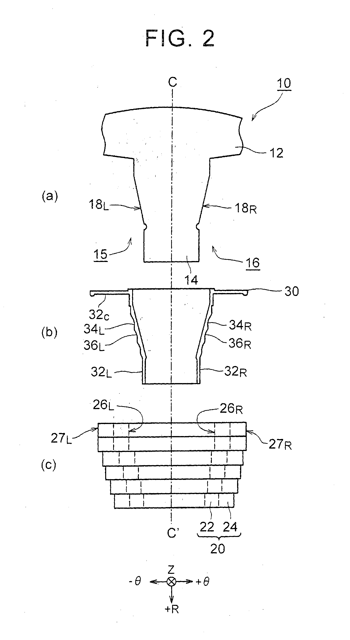
[0027]FIG. 1 and FIG. 2 are diagrams that illustrate the configuration of a rotating electric machine stator 10 that is used in a rotating electric machine that is mounted in a vehicle. In the following, the rotating electric machine stator 10 is referred to as “stator 10” unless otherwise stated. In FIG. 1, (a) is a perspective view of a stator core 11, and (b) is a perspective view of an insulator 30 that is fitted on each tooth 14 of the stator core 11 that is shown in (a). In FIG. 2, (a) is a top view of the tooth 1...


PUM


Abstract

A stator of a rotating electric machine includes a stator core, a plurality of insulators and a plurality of concentrated winding coils. The stator core includes an annular yoke and a plurality of teeth. The insulators are located along outer peripheral wall surfaces of the teeth. Each of the insulators includes a plurality of first surfaces and a plurality of second surfaces. The second surfaces connect the first surfaces. The coils are fitted on the teeth on which the insulators have been placed from a radially inner side thereof. The first surfaces of each of the insulators are in contact with inner peripheral surfaces of the coil that is placed on the outer periphery of the insulator.

Description

BACKGROUND OF THE INVENTION[0001]1. Field of the Invention[0002]The present invention relates to a rotating electric machine stator, and more particularly, to a rotating electric machine stator in which coils are wound via insulators.[0003]2. Description of Related Art[0004]When coils of a rectangular wire are wound via insulators, the insulators are preferably as thin as possible in order to improve the space factor of the windings as long as the insulating performance of the insulators is ensured.[0005]Japanese Patent Application Publication No. 2012-222944 (JP 2012-222944 A) discloses a stator in which rectangular wires are wound around teeth that protrude inward from a yoke portion of a stator core via insulators. In the stator, the thickness of the insulators is varied depending on the relative positional relationship between the rectangular wires and the teeth.[0006]It is stated in Japanese Patent Application Publication No. 2013-162565 (JP 2013-162565 A) that concentrated win...

Claims


Application Information

Patent Timeline
IPC IPC(8): H02K3/32H02K3/52H02K3/18
CPCH02K3/325H02K3/522H02K3/18H02K2203/12
Inventor MIYAMOTO, TOMOHIKOTSUJI, TAKESHINAKAJIMA, DAI
Owner TOYOTA JIDOSHA KK
Why Eureka
Try Eureka