
Interdental cleaning instrument

a cleaning instrument and interdental technology, applied in the field of interdental cleaning instruments, can solve the problems of reducing the back teeth and the inability to clean the interdental space, and achieve the effect of convenient insertion of cleaning parts

Active Publication Date: 2021-06-08
KOBAYASHI PHARMA CO LTD
View PDF24 Cites 0 Cited by
  • Summary
  • Abstract
  • Description
  • Claims
  • Application Information

AI Technical Summary

Benefits of technology

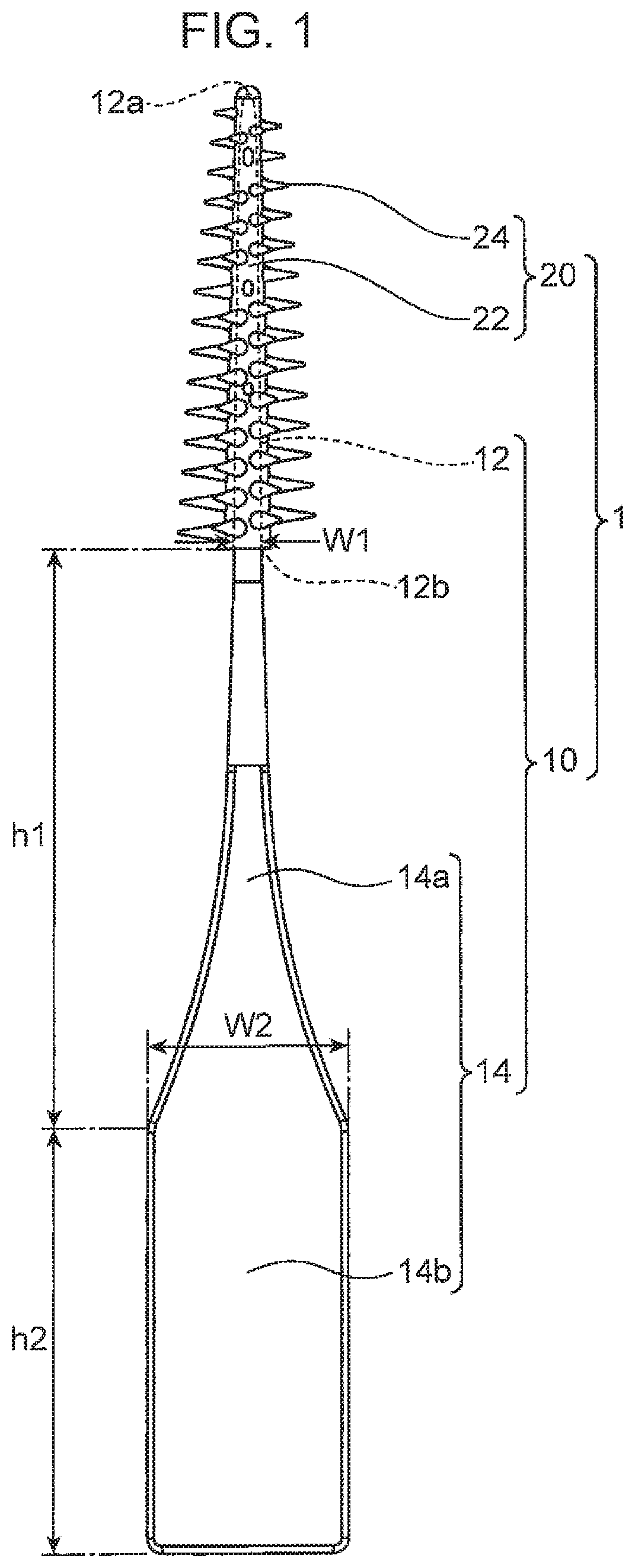
[0007]An object of the present invention is to provide an interdental cleaning instrument that enables easy insertion of a cleaning part in the space between back teeth.
[0008]In order to solve the aforementioned problem, it is conceivable to reduce the strength of the shaft part. In this way, after the tip of the cleaning part comes into contact with the outer surface of the back teeth, the shaft part is inserted in the present posture thereof back into the oral cavity, so that the cleaning part is inserted while the shaft part is flexurally deformed so that the tip of the shaft part (the tip of the cleaning part) is directed towards the back of the space between the back teeth. Therefore, the operation of adjusting the posture of the shaft part when the tip of the cleaning part is in contact with the outer surface of the back teeth is not required. However, when the strength of the shaft part is reduced, the elastic restoring force of the shaft part during the insertion of the cleaning part in the space between the back teeth, that is, the force pressing the cleaning part against the outer surface of the back teeth is reduced. As a result, the ability to clean the interdental space and the back teeth is reduced. Further, where the strength of the shaft part is too low, when the shaft part is further inserted in the present posture thereof from the state in which the tip of the cleaning part is in contact with the outer surface of the back teeth toward the back of the oral cavity, flexural deformation of the shaft part such that the tip of the shaft part is directed towards the back of the space between the back teeth is less likely to occur.
[0009]Accordingly, the inventors of the present invention have conceived of the possibility of improving both the insertability of the cleaning part into the space between the back teeth and the cleaning property of the interdental space by setting the strength of the portion of the base part that is located relatively close to the insertion end section of the shaft part and the strength of the portion of the base part that is located relatively far from the insertion end section of the shaft part within the respective specific ranges.

Problems solved by technology

As a result, the ability to clean the interdental space and the back teeth is reduced.

Method used


Image

  • Interdental cleaning instrument
  • Interdental cleaning instrument
  • Interdental cleaning instrument

Examples


example 1

[0047 is the interdental cleaning instrument 1 of the above embodiment. In Example 2, in the interdental cleaning instrument 1 shown in FIG. 5, the grip part 14 is also covered with the styrene elastomer. Example 3 is the interdental cleaning instrument 1 shown in FIG. 6. In these Examples 1 to 3, the base part 10 was formed of polypropylene, and the cleaning part 20 was formed of a styrene elastomer having a Shore A hardness of A40.

[0048]Example 4 is an instrument of the same shape as the interdental cleaning instrument 1 shown in FIG. 6; in this instrument, the base part 10 is formed of an ABS resin and the cleaning part 20 is formed of a styrene elastomer having a Shore A hardness of A40. Example 5 is an instrument of the same shape as the interdental cleaning instrument 1 shown in FIG. 6; in this instrument, the base part 10 is formed of a polybutylene terephthalate (PBT) resin and the cleaning part 20 is formed of a silicone having a Shore A hardness of A40.

[0049]The test resul...


PUM


Abstract

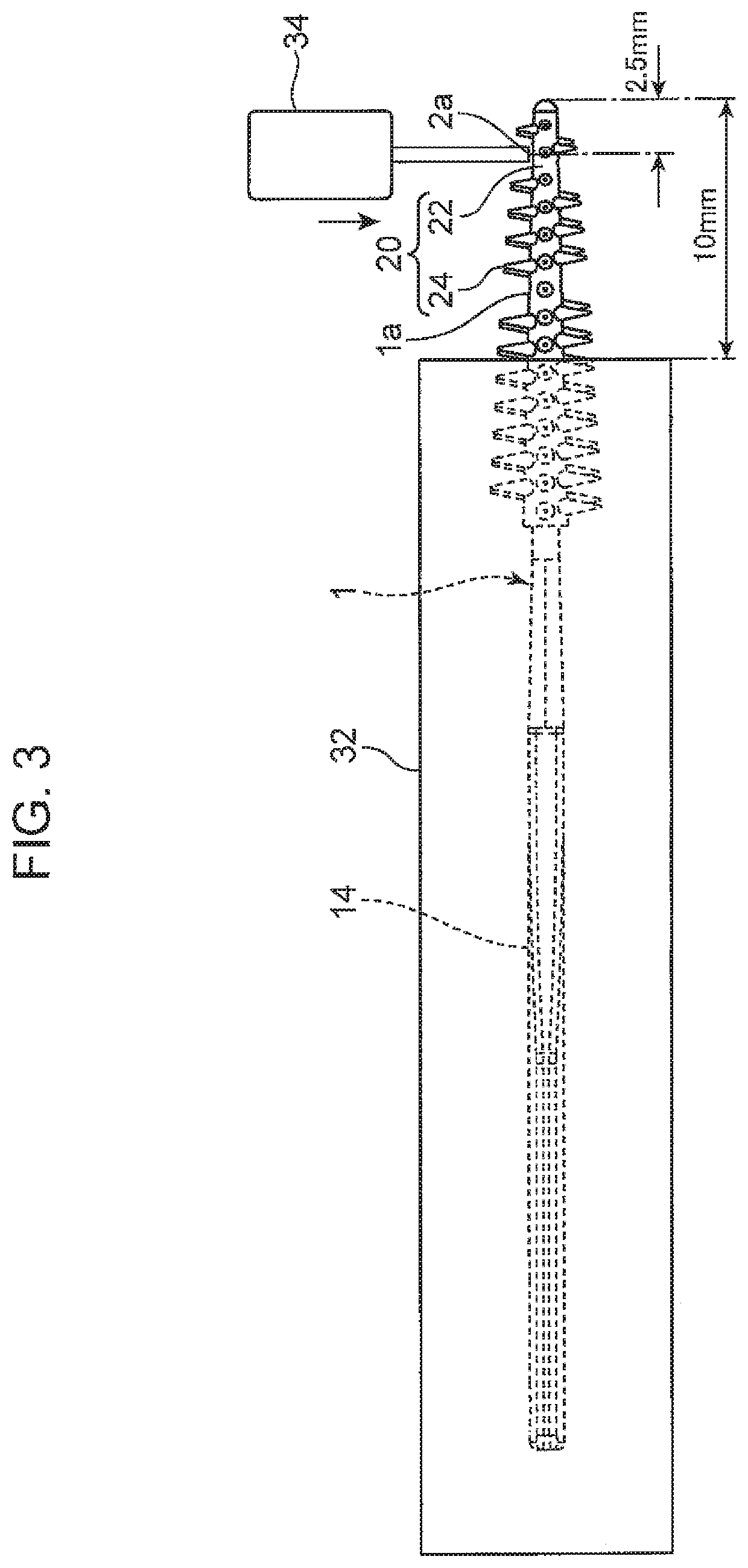
An interdental cleaning instrument is equipped with a base part and a cleaning part. The base part has a shaft part and a grip part. At least the shape of the base part is set in a manner such that a first pressing force required to press a portion spaced 2.5 mm apart from a tip of the cleaning part in 10 mm is 0.3 N or more and 1.4 N or less in a state in which a portion spaced 10 mm apart from the tip of the cleaning part is fixed, and a second pressing force required to press a portion spaced 8.0 mm apart from the tip of the cleaning part in 10 mm is 0.5 N or more and 2.5 N or less in a state in which a portion spaced 35 mm apart from the tip of the cleaning part is fixed.

Description

CROSS REFERENCE TO RELATED APPLICATIONS[0001]This application is a 371 National Stage application of PCT / JP2015 / 068407, which has an international filing date Jun. 25, 2015, which claims priority to Japanese Patent Application No. 2015-006847, filed Jan. 16, 2015, which are hereby incorporated herein by reference in their entirety.TECHNICAL FIELD[0002]The present invention relates to an interdental cleaning instrument.BACKGROUND ART[0003]An interdental cleaning instrument for cleaning an interdental space is known. For example, Patent Literature 1 discloses an interdental cleaning instrument including a base part having a shape extending in a specific direction and a cleaning part composed of an elastomer having a hardness lower than the hardness of the base part. The base part has a shaft part having a shape that can be inserted into an interdental space and a grip part having a shape that can be gripped by fingers. The cleaning part has a shape covering an outer peripheral surface...

Claims


Application Information

Patent Timeline
Patent Type & Authority Patents(United States)
IPC IPC(8): A61C15/00A61C15/02A46B5/00
CPCA61C15/02A46B5/00A46B2200/108A61C2201/00A46B5/02
Inventor KIKKAWA, TASUKU
Owner KOBAYASHI PHARMA CO LTD
Learn More