Heat-shrinkable plastic element, composite preform, and composite container

a plastic element and shrinkable technology, applied in the direction of rigid containers, synthetic resin layered products, packaging, etc., can solve the problems of difficult to obtain containers including portions, limit the means for obtaining containers having various functions and characteristics, etc., to improve the insertability of preforms and improve the production efficiency of composite preforms.

Pending Publication Date: 2021-07-01
MITSUBISHI CHEM CORP +1
View PDF0 Cites 0 Cited by
  • Summary
  • Abstract
  • Description
  • Claims
  • Application Information

AI Technical Summary

Benefits of technology

The heat-shrinkable plastic element in this patent can make it easier to insert a preform, which can improve the manufacturing of composite preforms and containers.

Problems solved by technology

Commonly, a preform is just molded into a container in conventional biaxial stretch—blow molding, which limits means for obtaining a container having various functions and characteristics (such as barrier properties and heat-retaining properties) to, for example, change of a material constituting the preform.
It is especially difficult to obtain a container including portions (such as a body part and a bottom part) having different functions and characteristics.

Method used


Image

  • Heat-shrinkable plastic element, composite preform, and composite container
  • Heat-shrinkable plastic element, composite preform, and composite container
  • Heat-shrinkable plastic element, composite preform, and composite container

Examples


example 1

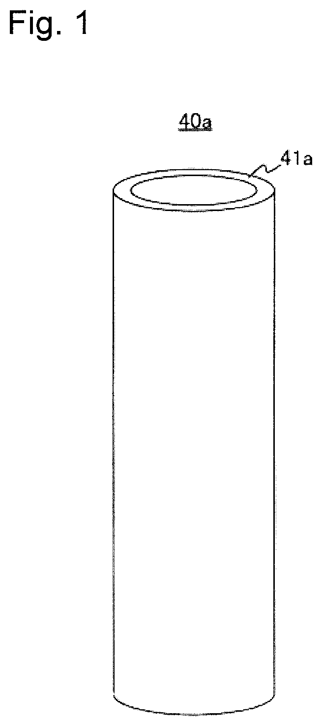
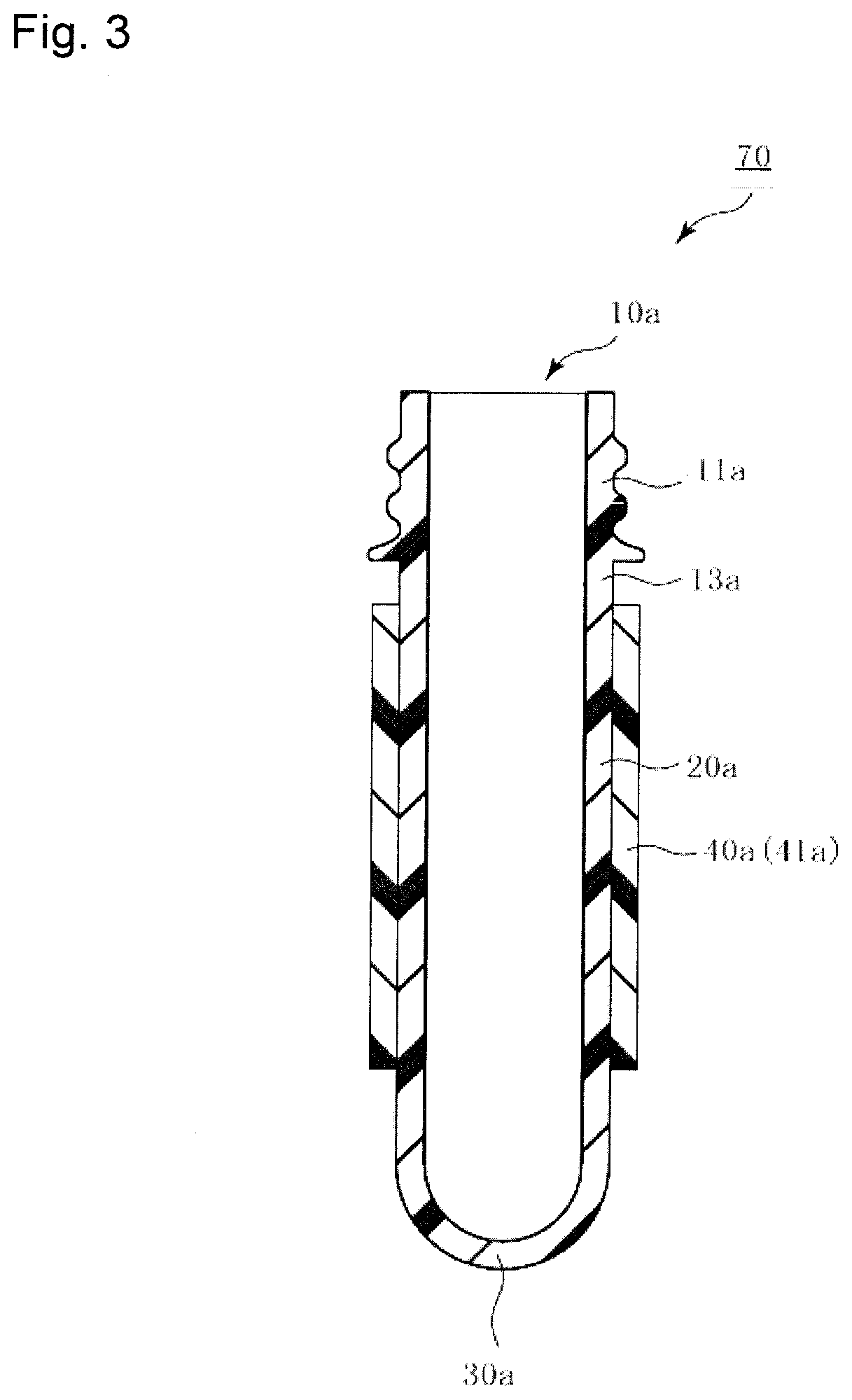
[0147]A mixture of 95 mass % Himilan 1706 (manufactured by DU PONT-MITSUI POLYCHEMICALS CO., LTD., MFR: 0.9 g / 10 min., storage modulus at 25° C.: 3.8×10⁸ Pa) as (A) an ionomer resin, and 5 mass % WINTEC WFX4TA (manufactured by Japan Polypropylene Corporation, metallocene polypropylene, MFR: 7.0 g / 10 min., storage modulus at 25° C.: 1.0×10⁹ Pa) as (B) an olefin resin was melt-extruded by a single screw extruder using an annular die, to be molded into a non-elongated tube having an inner diameter of 16.6 mm, and next this non-elongated tube was heated by hot water, and pressurized by compressed gas from the inside thereof, to be elongated, and thus a heat-shrinkable plastic element having a cylindrical shape without a bottom was made. The heat-shrinkable plastic element had an inner diameter of 28.7 mm, and a thickness of 307 μm.

example 2

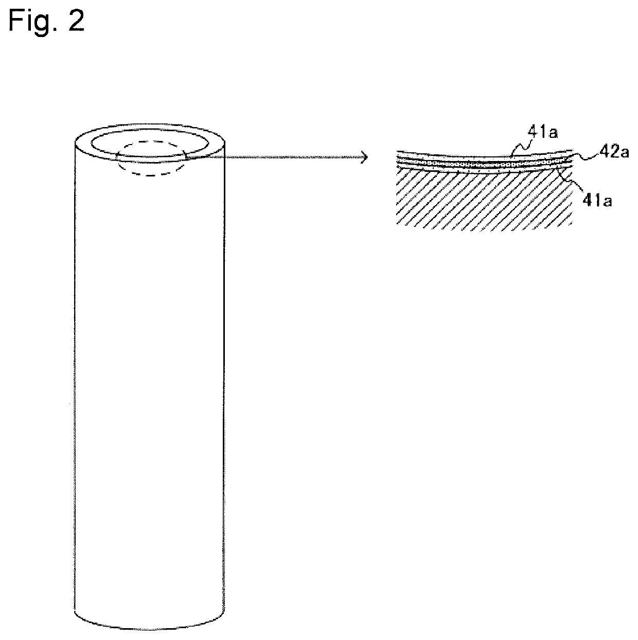
[0148]A mixture of 95 mass % Himilan 1706 as (A) the ionomer resin, and 5 mass % WINTEC WFX4TA as (B) the olefin resin used for outermost layers, a 100 mass % polyolefin adhesive resin (ADMER SF731 manufactured by Mitsui Chemicals, Inc) as adhesive layers, and a mixture of a 100 mass % ethylene-vinyl alcohol copolymer (EVAL SP482B manufactured by Kuraray Co., Ltd) as a gas-barrier layer for a middle layer were each melt-extruded by a single screw extruder using a three-kind five-layer annular die, and were molded into a non-elongated tube having an inner diameter of 18.3 mm, and next this non-elongated tube was heated by hot water, and pressurized by compressed gas from the inside thereof, to be elongated, and thus a heat-shrinkable plastic element having a cylindrical shape without a bottom was made. The heat-shrinkable plastic element had an inner diameter of 28.7 mm, and a thickness of 345 μm (each outermost layer: 132 μm, each adhesive layer: 17 μm, middle layer: 47 μm).


PUM

PropertyMeasurementUnit
storage modulusaaaaaaaaaa
dynamic friction coefficientaaaaaaaaaa
specific gravityaaaaaaaaaa

Abstract

A heat-shrinkable plastic element that can notably improve insertability of a preform is provided. The heat-shrinkable plastic element is disposed on at least part of the outside of a preform, the preform including a mouth part, a body part linked to the mouth part, and a bottom part linked to the body part, the heat-shrinkable plastic element including: at least a layer containing (A) an ionomer resin and (B) an olefin resin as essential constituents, wherein the heat-shrinkable plastic element has a storage modulus at 25° C. of at least 4.0×10⁸ Pa, and the dynamic friction coefficient between the heat-shrinkable plastic element and the preform is at most 1.1.

Description

TECHNICAL FIELD[0001]The present invention relates to a heat-shrinkable plastic element, a composite preform including the heat-shrinkable plastic element, and a composite container that is a blow-molded product of the composite preform.BACKGROUND ART[0002]A plastic container has come into common use recently as a container for keeping fluid of food and drink etc. therein.[0003]Such a plastic container for keeping fluid therein can be produced by inserting a preform into a metal mold, and then biaxial stretch—blow molding this preform (biaxial stretch blow molding).[0004]For example, preforms including a monolayer material, a multilayer material, or a blend material of polyethylene terephthalate (PET), polypropylene (PP), etc. are conventionally used for production of plastic containers.[0005]Commonly, a preform is just molded into a container in conventional biaxial stretch—blow molding, which limits means for obtaining a container having various functions and characteristics (such...

Claims


Application Information

Patent Timeline
Patent Type & Authority Applications(United States)
IPC IPC(8): B65D23/08B29C49/22B29C61/02B65D1/02
CPCB65D23/0864B29C49/22B29L2031/7158B65D1/0223B29C61/02B29C49/0005B29C49/02B29C61/0616B29C63/42B32B1/08B32B27/32B32B27/308B32B27/327B32B27/325B32B27/306B32B27/36B32B27/34B32B27/20B32B27/22B32B27/08B32B7/12B32B23/08B32B2439/00B32B2597/00B32B2307/402B32B2307/412B32B2307/71B32B2307/7244B32B2307/732B32B2307/736B32B2307/744B29K2067/003B29K2995/0049B29K2105/0094B29K2995/0012B29K2995/0097B29K2023/12B32B1/00B32B3/08B32B27/302B32B2270/00B32B3/30B32B3/02B32B23/04B32B27/28
Inventor IKEDA, KEITAODAWARA, KOJIMIWA, MASAKIHASHIMOTO, DAICHISUGA, YUSUKEMIYAWAKI, TAKUMA
Owner MITSUBISHI CHEM CORP
Why Eureka
Try Eureka