
Spring guide and suspension device

a technology of spring guide and spring seat, which is applied in the direction of shock absorbers, wound springs, transportation and packaging, etc., can solve the problems of time and labor for insertion of shock absorber devices into the hole of lower spring seats, and the gate trace comes into contact with the housing of shock absorber devices, so as to improve the insertability of shock absorbers

Pending Publication Date: 2022-01-27
KYB CORP
View PDF0 Cites 0 Cited by
  • Summary
  • Abstract
  • Description
  • Claims
  • Application Information

AI Technical Summary

Benefits of technology

The present invention aims to make it easier to insert a shock absorber into a spring guide.

Problems solved by technology

When the lower spring seat is formed by an injection molding, if a gate trace (a burr) of an injection mold is formed on an inner circumferential surface of the hole, as the shock absorber device is to be inserted into the hole of the lower spring seat, there is a risk in that the gate trace comes into contact with the housing of the shock absorber device.
As a result, there is a problem in that the insertion of the shock absorber device into the hole of the lower spring seat takes time and labor.

Method used


Image

  • Spring guide and suspension device
  • Spring guide and suspension device
  • Spring guide and suspension device

Examples


Embodiment Construction

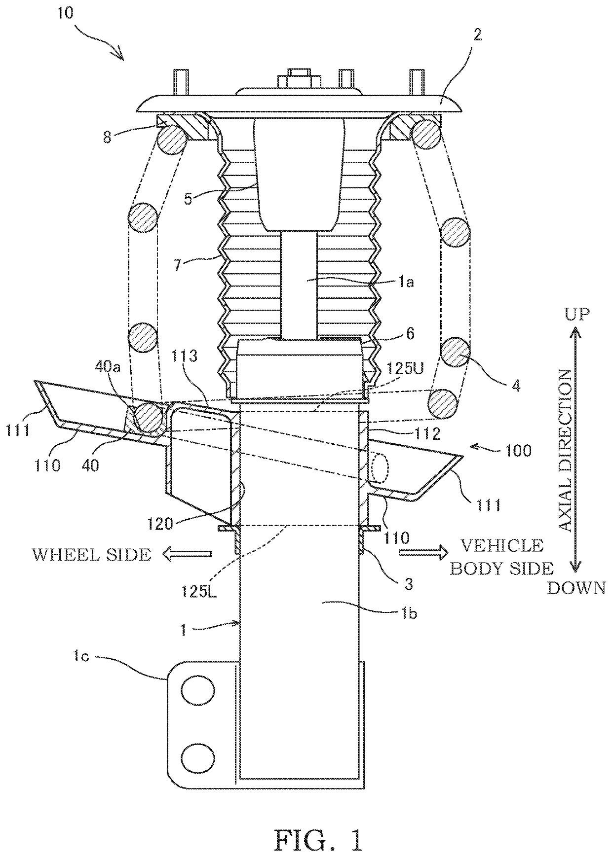
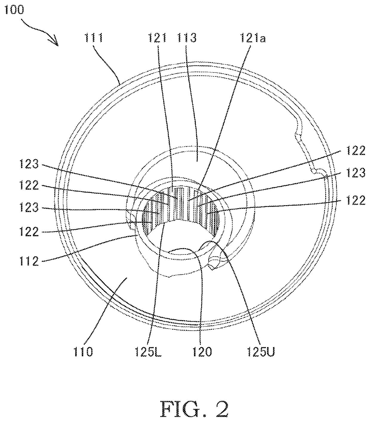
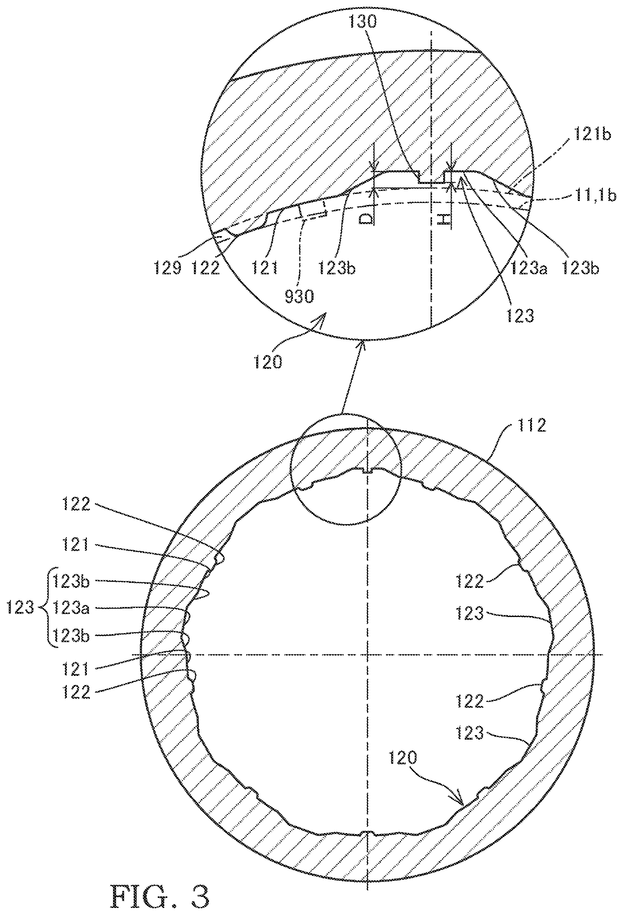
[0016]A spring guide 100 and a suspension device 10 according to an embodiment of the present invention will be described with reference to the drawings.

[0017]As shown in FIG. 1, the suspension device 10 is a device for stably suspending a vehicle body by being installed on an automobile (not shown), by positioning a wheel (not shown), and by absorbing impacts and vibrations received from a road surface during a travelling of a vehicle by generating a damping force.

[0018]The suspension device 10 is provided with: a strut type shock absorber 1 that is provided between the vehicle body and the wheel; an upper mount 2 that is attached to a tip end of a piston rod (hereinafter, referred to as a rod) 1a of the shock absorber 1; the spring guide 100 that is attached to an outer circumferential surface of a cylinder 1b of the shock absorber 1; a coil spring 4 that is provided between the spring guide 100 and the upper mount 2 and that elastically supports the vehicle body; a bump stopper 5...


PUM


Abstract

A spring guide includes: a base portion configured to support a coil spring; and an opening portion provided so as to penetrate through the base portion, the opening portion being configured such that a shock absorber is inserted into the opening portion, the opening portion is provided with: protruded portions protruding out from an inner circumferential surface of the opening portion, the protruded portions being configured to support the shock absorber; and a recessed portion recessed in the inner circumferential surface of the opening portion, a plurality of the protruded portions are arranged along a circumferential direction of the opening portion, and a gate trace of an injection mold is formed in the recessed portion.

Description

TECHNICAL FIELD[0001]The present invention relates to a spring guide and a suspension device.BACKGROUND ART[0002]There is a known strut type dumper (suspension device) in which a coil spring, which is disposed around a shock absorber device (a shock absorber) so as to be concentrical therewith, is provided (see JP2017-172801A). The coil spring is arranged between an upper spring seat and a lower spring seat of the dumper. A hole (an opening portion) for receiving a housing of the shock absorber device is provided in the lower spring seat (a spring guide).SUMMARY OF INVENTION[0003]When the lower spring seat is formed by an injection molding, if a gate trace (a burr) of an injection mold is formed on an inner circumferential surface of the hole, as the shock absorber device is to be inserted into the hole of the lower spring seat, there is a risk in that the gate trace comes into contact with the housing of the shock absorber device. As a result, there is a problem in that the inserti...

Claims


Application Information

Patent Timeline
Patent Type & Authority Applications(United States)
IPC IPC(8): B60G15/06F16F9/54F16F9/58F16F1/12B60G11/16
CPCB60G15/063F16F9/54B60G2204/12422F16F1/126B60G11/16F16F9/58F16F1/12F16F2230/0005F16F2230/0041B60G2202/312B60G2204/1242
Inventor KURIHARA, KENTA
Owner KYB CORP
Learn More