Catheter

a catheter and catheter technology, applied in the field of catheters, can solve the problems that the catheter described above cannot be inserted into such lesions smoothly, and achieve the effects of improving the insertability, improving the surface roughness of the distal region, and improving the insertability into the stenosis

Inactive Publication Date: 2020-09-03
ASAHI INTECC CO LTD
View PDF0 Cites 0 Cited by
  • Summary
  • Abstract
  • Description
  • Claims
  • Application Information

AI Technical Summary

Benefits of technology

[0012]According to the first aspect of the present disclosure, as the catheter comprises a main body, and a distal portion joined to a distal end of the main body and made of a resin including metal or metal compound, wherein the distal portion includes a distal region and a proximal region disposed in a proximal side of the distal region, and a hardness of the distal region is higher than a hardness of the proximal region, the proximal region has a followability to a medical device such as a guidewire used together, and the catheter has an effect of improving insertability into the stenosis and an effect of preventing the collapse of the distal portion of the catheter when the catheter is inserted into the stenosis.
[0013]According to the second aspect of the present disclosure, as a surface roughness of the distal region is greater than a surface roughness of the proximal region in the catheter of the first aspect of the present disclosure, in addition to the effects of the catheter of the first aspect of the present disclosure, it is capable of further improving insertability into the stenosis to reduce the contact resistance between the hard distal region and the stenosis.
[0014]According to the third aspect of the present disclosure, as a degree of exposure of the metal or metal compound on the surface of the distal region is higher than a degree of exposure of the metal or metal compound on the surface of the proximal region in the catheter of the first aspect or the second aspect of the present disclosure, in addition to the effects of the catheter of the first aspect or the second aspect of the present disclosure, it is capable of improving insertability into the stenosis to reduce the contact resistance between the distal region and the stenosis by utilizing the metal or metal compound contained.
[0015]Further, according to the fourth aspect of the present disclosure, as metal or metal compound includes radiopaque metal in the catheter of any one of the first aspect to the third aspect of the present disclosure, in addition to the effects of the catheter of any one of the first aspect to the third aspect of the present disclosure, it is capable of improving a visibility of the distal portion by adding a performance of a visibility.

Problems solved by technology

However, recently there is often the procedure for severe patients having CTO (Chronic Total Occlusion) or a lesion close to CTO, and the conventional catheter described above cannot be inserted into such lesions smoothly.

Method used


Image

  • Catheter
  • Catheter
  • Catheter

Examples


first embodiment

[0023]First of all, a first embodiment of the present disclosure will be described. The drawings used in the present embodiment are provided to facilitate understanding of the present disclosure, and the dimensions of the drawings may differ from actual dimensions.

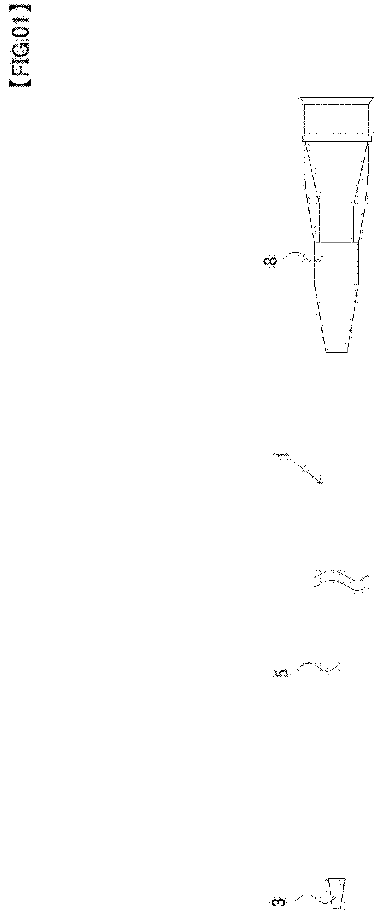
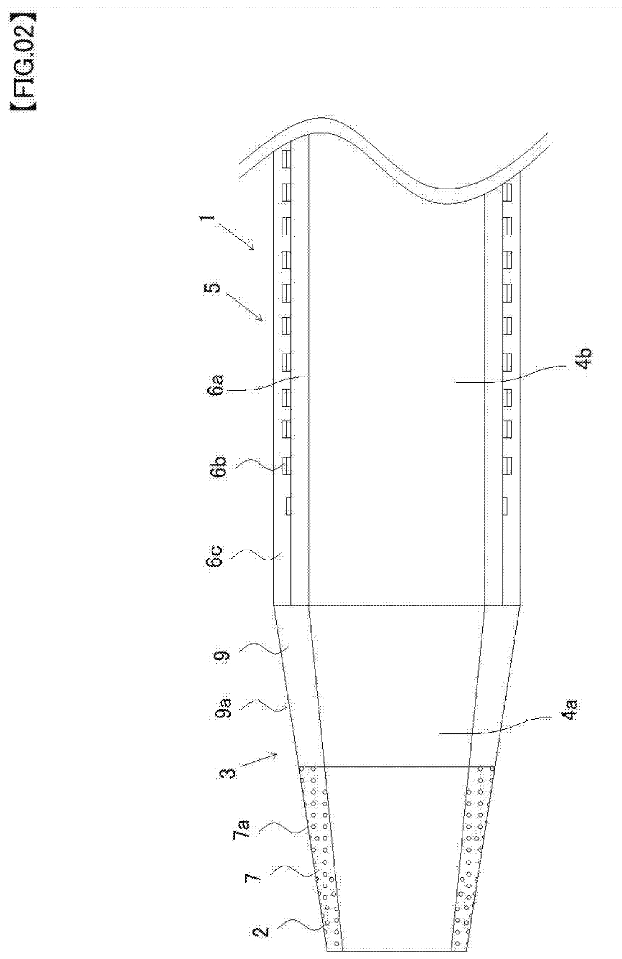
[0024]FIG. 1 is an overall view of the catheter of a first embodiment of the present disclosure, and FIG. 2 is a longitudinal sectional view around a distal portion of the catheter of the first embodiment.

[0025]As shown in FIG. 1, a catheter 1 of the present embodiment includes a catheter body 5 (corresponding to “a main body” of the present disclosure), a distal tip 3 (corresponding to “a distal portion” of the present disclosure) joined to a distal end of the catheter body 5, and a connector 8 joined to a proximal end of the catheter body 5.

[0026]The catheter body 5 includes an inner layer 6a, a braid 6b wound around an outer periphery of the inner layer 6a, and an outer layer 6c covering the inner layer 6a and the braid...

second embodiment

[0040]Next, a second embodiment of the present disclosure will be described. The drawings used in the present embodiment are provided to facilitate understanding of the present disclosure, and the dimensions of the drawings may differ from actual dimensions.

[0041]Hereinafter the second embodiment of the present disclosure will be described, and the overall view of the catheter will not be described because it is similar to FIG. 1. Portions common to the first embodiment will be denoted by the same reference numerals, and descriptions of the portions will be omitted.

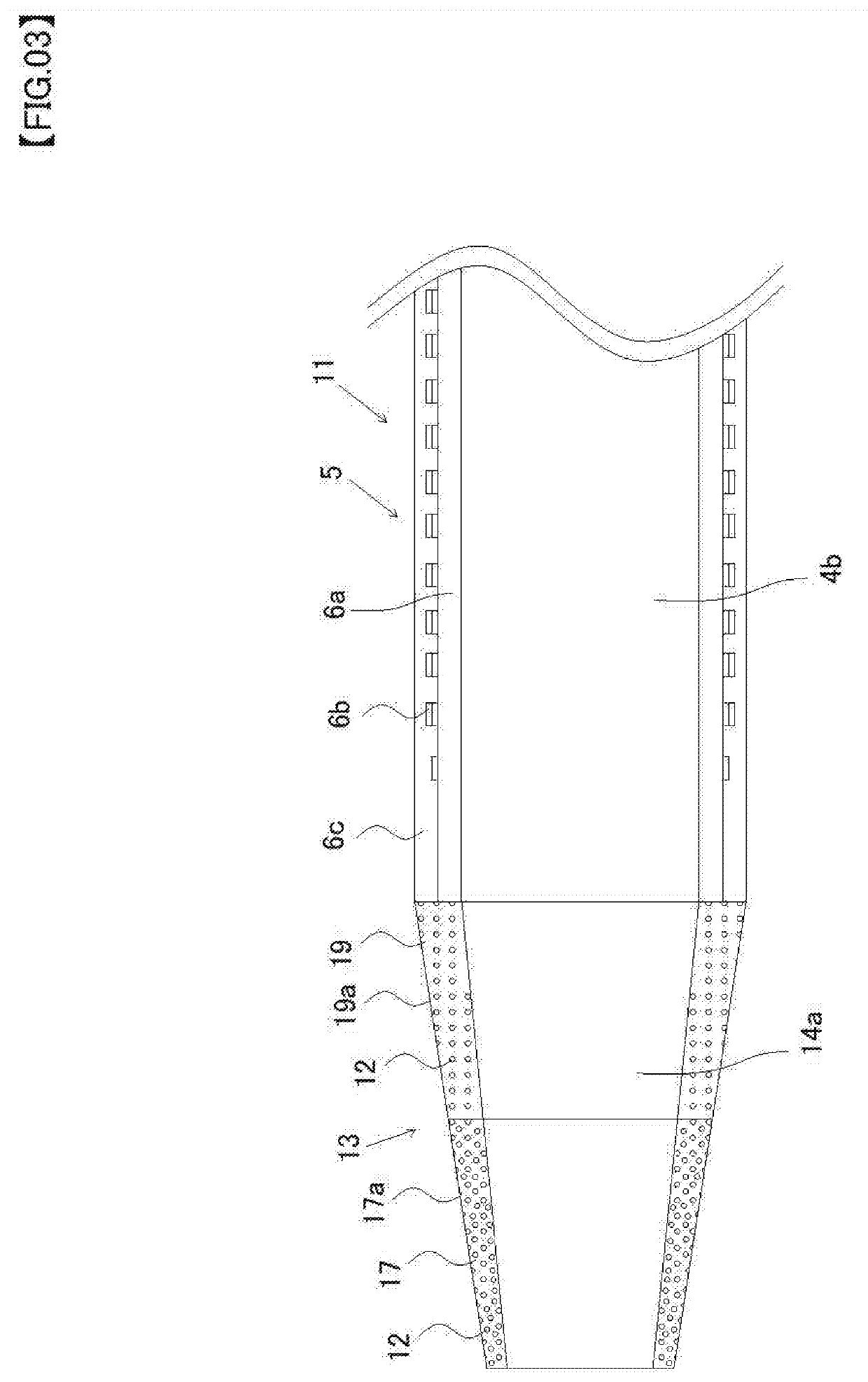
[0042]The catheter 11 of the second embodiment differs from the catheter 1 of the first embodiment in a distal tip configuration. That is, in the distal tip 3 of the catheter 1 of the first embodiment, powder of biocompatible metal or metal compound was mixed only in the distal region 7, not mixed in the proximal region 9.

[0043]In contrast, in the distal tip of the present embodiment, powder of biocompatible metal or meta...

third embodiment

[0053]Next, a third embodiment of the present disclosure will be described. The drawings used in the present embodiment are provided to facilitate understanding of the present disclosure, and the dimensions of the drawings may differ from actual dimensions.

[0054]Hereinafter the third embodiment of the present disclosure will be described, and the overall view of the catheter will not be described because it is similar to FIG. 1. Portions common to the first embodiment will be denoted by the same reference numerals, and descriptions of the portions will be omitted.

[0055]The catheter 21 of the third embodiment differs from the catheter 11 of the second embodiment in condition of an outer surface of the distal tip of the catheter. That is, an outer surface 17a and an outer surface 19a of the distal tip 13 of catheter 11 of the second embodiment are smooth. In contrast, an outer surface of the distal tip of the present embodiment is irregular.

[0056]FIG. 4 is a longitudinal sectional vie...


PUM

PropertyMeasurementUnit
hardnessaaaaaaaaaa
surface roughnessaaaaaaaaaa
radiopaqueaaaaaaaaaa

Abstract

A catheter comprises a catheter body and a distal tip joined to a distal end of the catheter body and made of a resin including tungsten powder, wherein the distal tip includes a distal region and a proximal region disposed in a proximal side of the distal region, and a hardness of the distal region is higher than a hardness of the proximal region.

Description

CROSS REFERENCE TO RELATED APPLICATION[0001]This application is a continuation of International Application No. PCT / JP2018 / 002180 filed Jan. 25, 2018. The entire content of the priority application is incorporated herein by reference.TECHNICAL FIELD[0002]The present invention relates to a medical device, and specifically to a catheter used by inserting into a lumen of a blood vessel or the like of a patient.BACKGROUND ART[0003]A catheter used by inserting into a lumen of a blood vessel or the like of a patient is known. A physician performing a procedure inserts a guidewire into the lumen of the catheter, protrudes a distal end of the guidewire from a distal end of the catheter, leads the catheter to a lesion using the guide wire, and places a device such as a stent or an embolic coil in the lesion through the lumen of the catheter.[0004]A distal portion of the catheter used in the procedure is generally configured to be soft in order to improve a tracking performance to the guide w...

Claims


Application Information

Patent Timeline
Patent Type & Authority Applications(United States)
IPC IPC(8): A61M25/01A61M25/00
CPCA61M2025/006A61M25/0043A61M2025/09166A61M25/0133A61M25/0068A61M25/008A61M25/0108A61M25/0045A61M25/005A61M25/001A61M25/0053A61L29/02A61L29/18A61M2025/0063
Inventor KATSURADA, TAKEHARUOGIDO, MORITAKA
Owner ASAHI INTECC CO LTD
Why Eureka
Try Eureka