Mandibular subluxation device and method

a subluxation device and mandibular technology, applied in the field of mandibular subluxation device and method, can solve the problems of restrictive surgical access to the neck zone 3 and difficulty in proper exposur

Active Publication Date: 2016-11-24
ARDEN RICHARD L
View PDF3 Cites 5 Cited by
  • Summary
  • Abstract
  • Description
  • Claims
  • Application Information

AI Technical Summary

Benefits of technology

[0004]According to an embodiment, there is provided a mandibular subluxation device (MSD). The MSD comprises a first mandibular subluxation component including an upper plate and an upper tooth guide. The MSD further comprises a second mandibular subluxation component including a lower plate and a lower tooth guide connected to the lower plate. The first mandibular subluxation component is connected with the second mandibular subluxation component to allow relative longitudinal movement between the first and second mandibular subluxation components between a neutral position and at least one extended position. A ratchet mechanism acts between the first and second mandibular subluxation components. The ratchet assembly allows for movement of the second mandibular subluxation component from the neutral position to an extended position and inhibits movement of the second mandibular subluxation component from an extended position toward the neutral position.

Problems solved by technology

Surgical access to zone 3 of the neck can be restrictive due to the triangular bony confines of the vertical mandibular ramus and the mastoid process.
Proper exposure can be challenging particularly in the presences of a short neck, morbid obesity, a high carotid bifurcation or the need for extended carotid dissection above C2.

Method used


Image

  • Mandibular subluxation device and method
  • Mandibular subluxation device and method
  • Mandibular subluxation device and method

Examples


Embodiment Construction

[0017]The following description of the preferred embodiment(s) is merely exemplary in nature and is in no way intended to limit the invention, its application, or its uses.

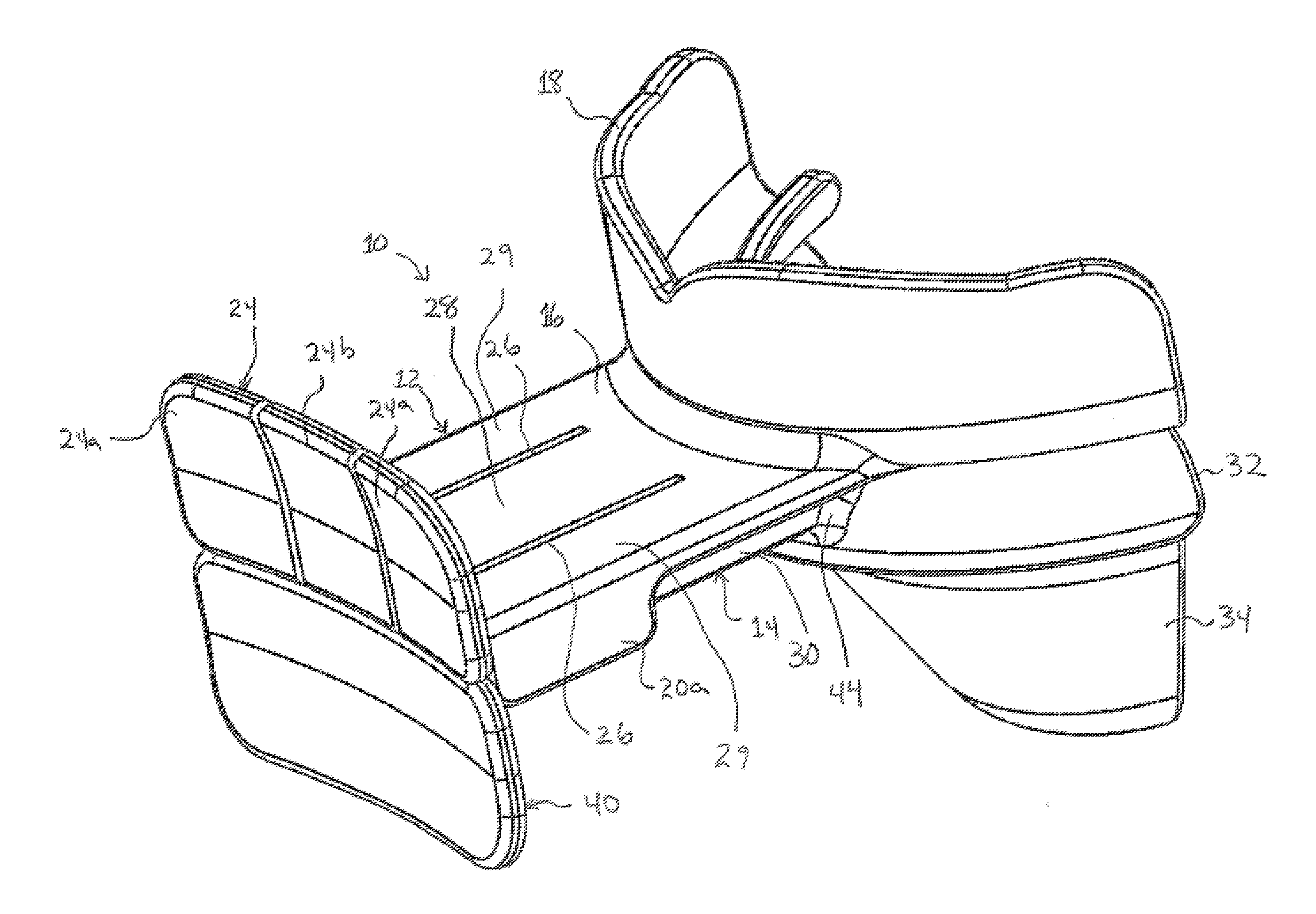
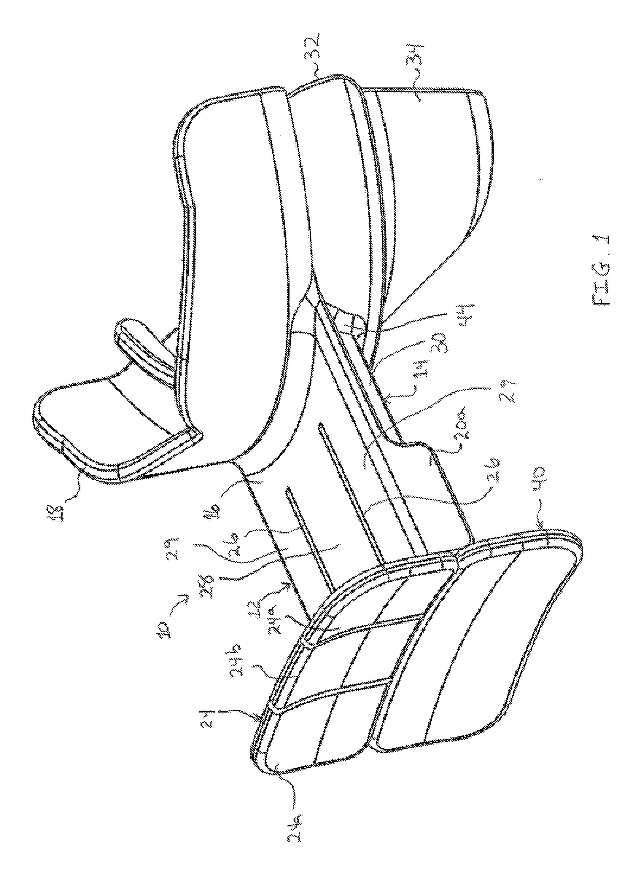
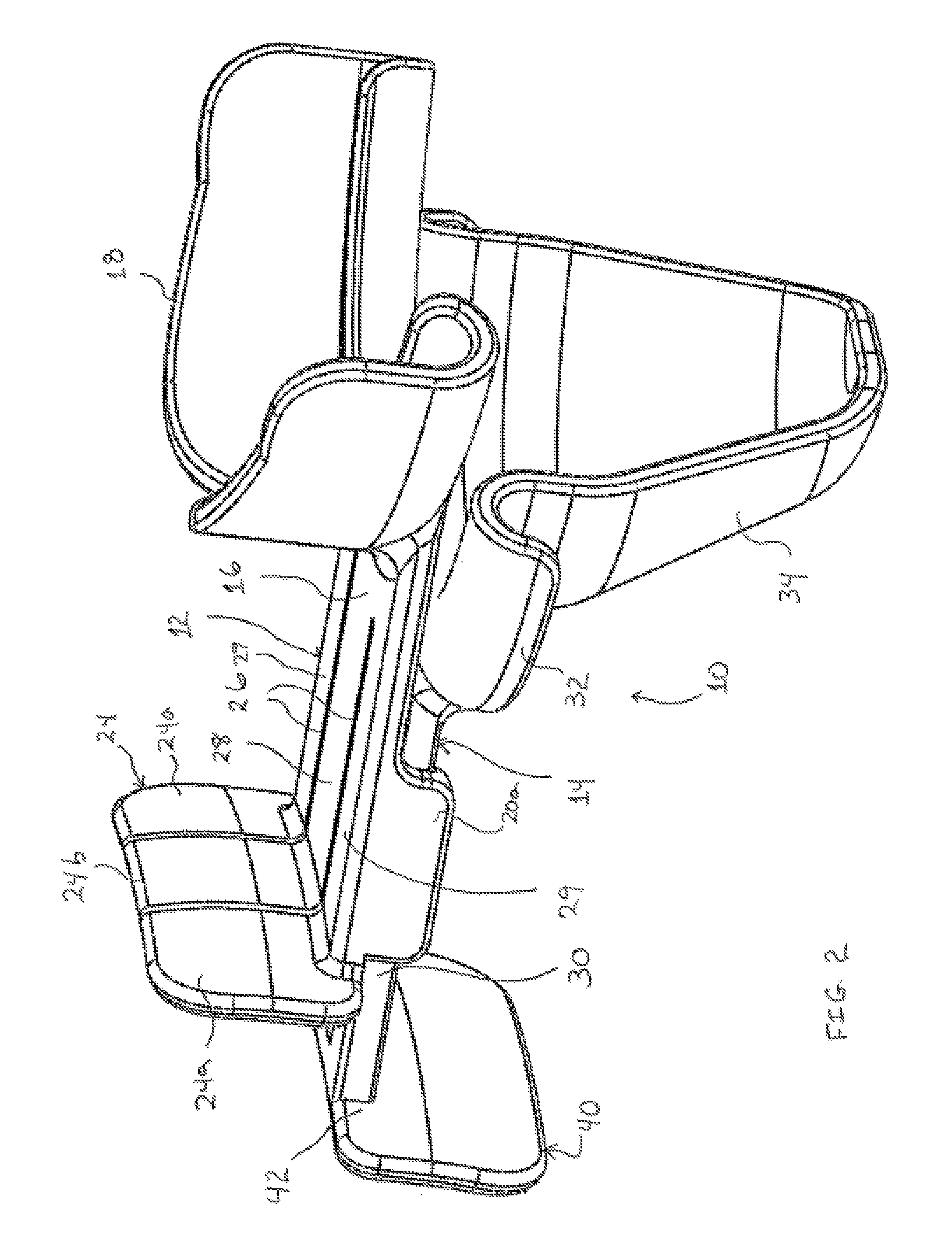
[0018]An embodiment of a mandibular subluxation device (MSD) is generally shown at 10. The MSD 10 may be useful to allow for anterior displacement of the vertical ramus of the mandible to provide access to the internal carotid artery and major cranial nerves. As best shown in FIG. 3, the MSD 10 may comprise a first or upper MSD component generally indicated at 12 and a second or lower MSD component, generally indicated at 14. The upper MSD component 12 may comprise an injection molded component. The lower MSD 14 component may comprise an injection molded component. The upper MSD component 12 and lower MSD component 14 may comprise any suitable material.

[0019]In the embodiment shown, the upper MSD component 12 has an upper plate 16. The upper plate 16 is preferably connected to an upper tooth guide 18. The upper to...


PUM


Abstract

A mandibular subluxation device (MSD) is provided. The device includes an upper MSD component and a lower MSD component. The upper MSD component includes and upper tooth guide connected to an upper plate having a pair of depending legs. The upper MSD component further includes an upper force receiving plate. The MSD also includes a lower MSD component. The lower MSD component includes a lower tooth guide connected to a lower plate. The lower MSD component further includes a lower force receiving plate. The upper and lower MSD components are connected in a way that allows relative longitudinal movement between the two components between a neutral position and a plurality of extended positions. A ratchet mechanism inhibits movement of the lower plate from any extended position toward the neutral position. The ratchet mechanism may be manually disengaged to allow the lower MSD component to return to the neutral position.

Description

[0001]This is a non-provisional patent application which claims the benefit of U.S. Provisional Patent Application Ser. No. 62 / 163,007 filed May 18, 2015, the disclosure of which is incorporated herein by reference in its entirety.FIELD OF THE INVENTION[0002]The present invention relates generally to a mandibular subluxation device and method.BACKGROUND OF THE INVENTION[0003]Surgical access to zone 3 of the neck can be restrictive due to the triangular bony confines of the vertical mandibular ramus and the mastoid process. Critical anatomic structures residing in the area, namely the internal carotid artery and major cranial nerves, require proper exposure to facilitate structural preservation and procedural implementation. Proper exposure can be challenging particularly in the presences of a short neck, morbid obesity, a high carotid bifurcation or the need for extended carotid dissection above C2. Mandibular subluxation can provide access to these anatomical structures for perform...

Claims


Application Information

Patent Timeline
Patent Type & Authority Applications(United States)
IPC IPC(8): A61B17/02A61C5/14A61B1/24
CPCA61B17/025A61C5/14A61B1/24A61B17/24A61B90/16A61B2017/00407
Inventor ARDEN, RICHARD L.GOODMAN, JOHN F.
Owner ARDEN RICHARD L
Why Eureka
Try Eureka