Filter Insert for a Fluid, in Particular Transmission Oil

Active Publication Date: 2016-11-24
MANN HUMMEL GMBH
View PDF4 Cites 0 Cited by
  • Summary
  • Abstract
  • Description
  • Claims
  • Application Information

AI Technical Summary

Benefits of technology

The invention is a filter insert that reduces differential pressure and creates a laminar flow through its design. By only partially covering the filter body, it creates an additional outflow or inflow cross-section through which fluid can flow. The pleat edges are arranged perpendicular to the main flow direction, which facilitates a flow and prevents turbulence. This design also reduces the likelihood of fouling and clogging. Overall, it improves the performance of the filter insert.

Problems solved by technology

In practice, this leads to very high differential pressure.

Method used


Image

  • Filter Insert for a Fluid, in Particular Transmission Oil
  • Filter Insert for a Fluid, in Particular Transmission Oil
  • Filter Insert for a Fluid, in Particular Transmission Oil

Examples


Embodiment Construction

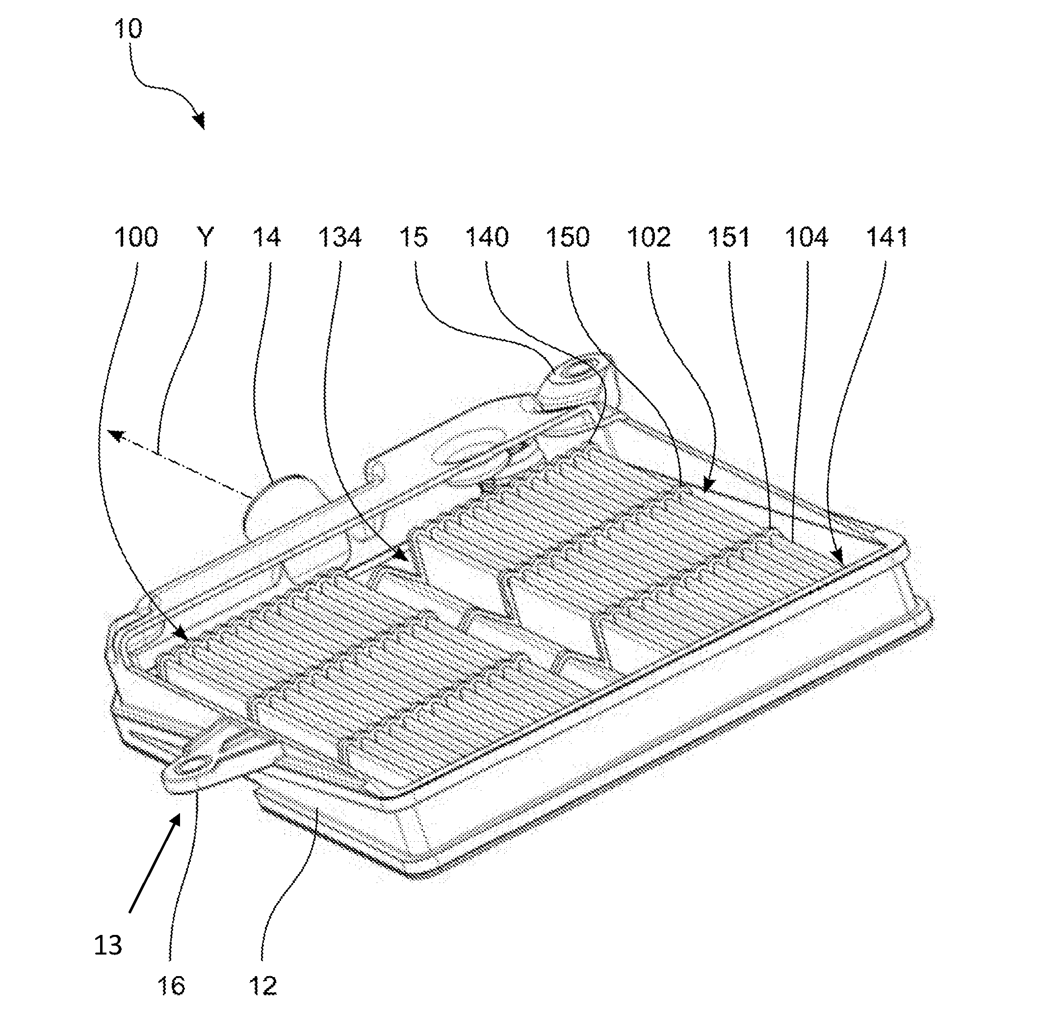
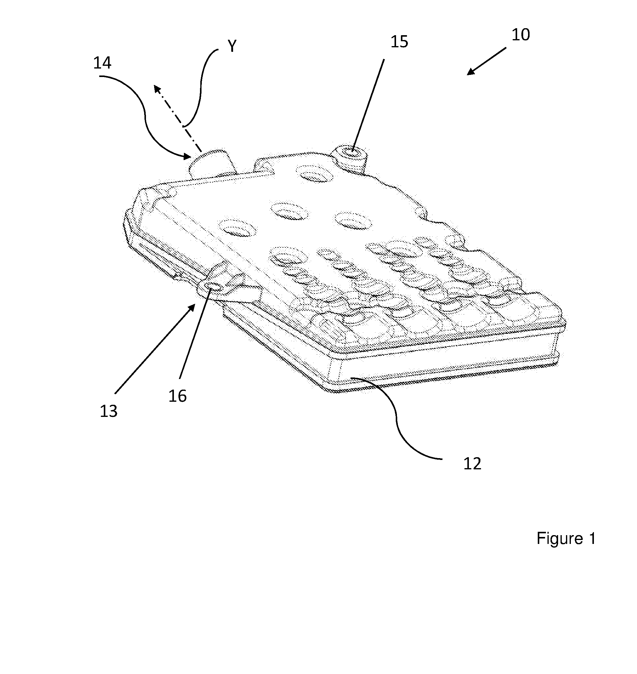
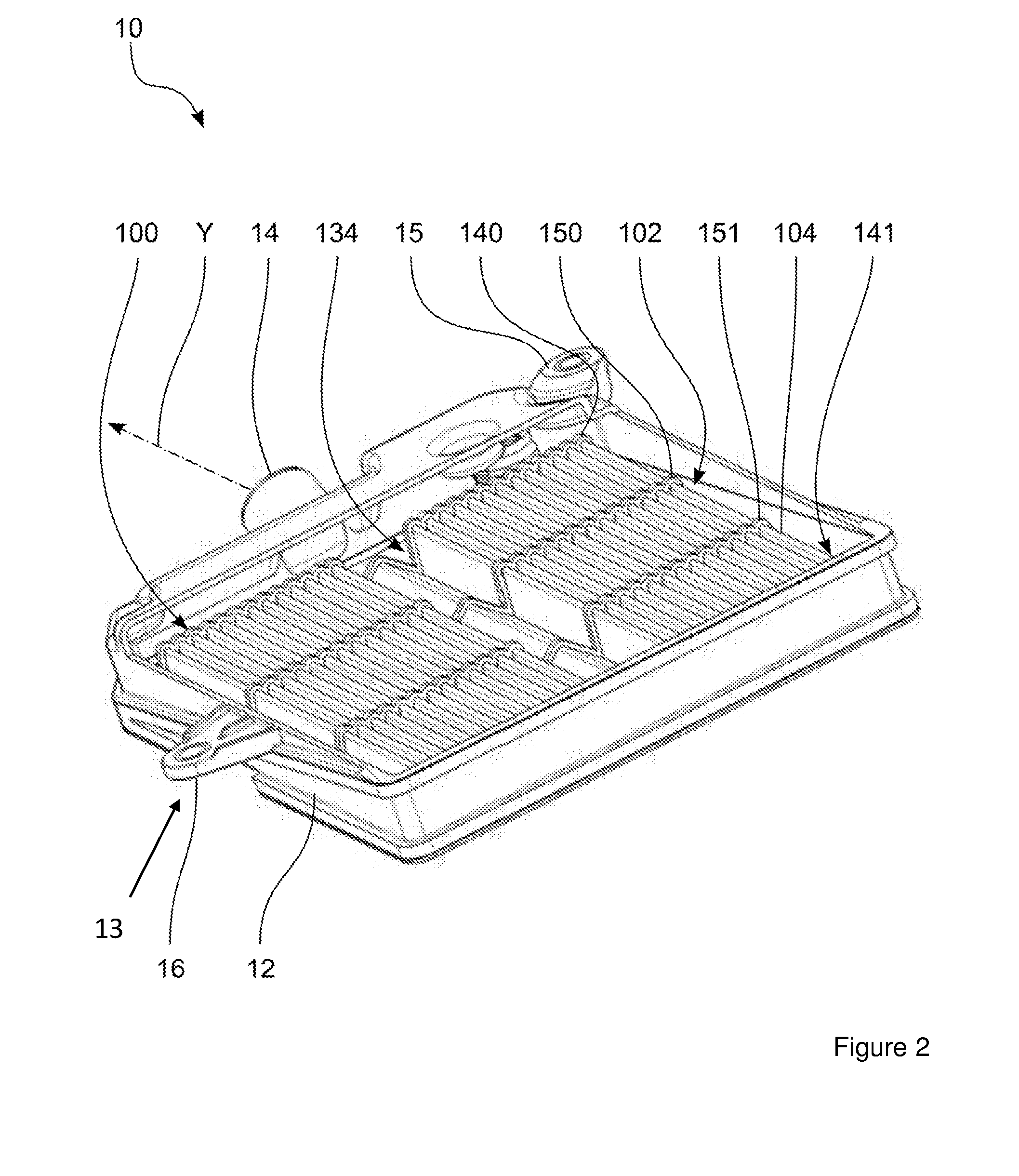
[0023]FIG. 1-3 illustrate a first embodiment of a transmission oil filter 10 according to the invention. The transmission oil filter 10 depicted in FIG. 1-3 works in the suction operation. The transmission oil filter 10 has a housing 12 and an outflow opening 14. The inflow opening, which is arranged at a right angle to the outflow opening 14 in the embodiment depicted (though this is not compulsory), is designated with the reference sign “13”.

[0024]FIG. 1 illustrates the transmission oil filter 10 in the closed state, while FIG. 2 illustrates the transmission oil filter 10 in the open state. Provided on the outside of the housing 12 are two fastening tabs 15, 16, in order to fasten the transmission oil filter 10 to the point of use thereof.

[0025]FIG. 2 illustrates the transmission oil filter 10 in the open state, and FIG. 3 illustrates a sectional view through the transmission oil filter 10 of FIG. 1. A filter insert 100 is inserted into the transmission oil filter 10. The filter i...


PUM

PropertyMeasurementUnit
Angleaaaaaaaaaa
Angleaaaaaaaaaa
Shapeaaaaaaaaaa

Abstract

A filter insert for a filter for filtering a fluid having] an inflow surface, and outflow surface, and a main throughflow direction. A filter body of the insert has a filter medium with pleats forming a pleated bellows, are arranged perpendicular to the main throughflow direction. A first number of the pleat edges form the outflow surface and a second number of the pleat edges on a pre-filtration side of the filtration body form the outflow surface. A first seal prevents the fluid from overflowing from the pre-filtration side to the post-filtration on a surface formed by a first number of of end face of the pleats. A second seal prevents the fluid from overflowing from the pre-filtration side to the post-filtration side on a surface formed by a second number of end faces of the pleats.

Description

TECHNICAL FIELD[0001]The invention relates to a filter insert for a filter for filtering a fluid, in particular transmission oil.BACKGROUND OF THE INVENTION[0002]The design of internal combustion engines seeks to make optimal use of the available installation space with a constant size. Accordingly, there is a requirement to design existing components with the smallest size possible, without including the functionality thereof.[0003]In particular, in the field of transmission oil filters, a design has been developed with which the surface through which the transmission oil is to flow is as large as possible, while, at the same time, the depth to be penetrated is relatively small. Usually, furthermore, the transmission oil flows out perpendicular to the inflow direction. In practice, this leads to very high differential pressure.SUMMARY[0004]The present invention addresses the problem of providing a filter insert and a filter for a fluid such as transmission oil, which has a compact ...

Claims


Application Information

Patent Timeline
IPC IPC(8): B01D29/21B01D35/00B01D29/11
CPCB01D29/213B01D29/111B01D35/005B01D2201/4023B01D2201/0415B01D2201/34B01D2201/122F16H57/0404B01D35/30B01D2201/127B01D29/07
Inventor EPLI, SVENJOKSCHAS, GUENTERPANZER, MARIUSEISENGRAEBER-PABST, JOBST
Owner MANN HUMMEL GMBH
Why Eureka
Try Eureka