Method and device for sealant coating inspection

a technology of sealant coating and inspection method, which is applied in the field of display technologies, can solve the problems of inability to identify the mark points, interfere with the actual graphic pattern of the sealant coating, and the sealant coating may be undetectable as being coated

Inactive Publication Date: 2016-11-24
BOE TECH GRP CO LTD +1
View PDF2 Cites 6 Cited by
  • Summary
  • Abstract
  • Description
  • Claims
  • Application Information

AI Technical Summary

Benefits of technology

[0031]The present disclosure provides a method and a device of inspecting a sealant coating on a substrate for various defects to reduce the rate of false defect identification and to improve the precision and reliability of the coating inspection results.
[0031]The present disclosure provides a method and a device of inspecting a sealant coating on a substrate for various defects to reduce the rate of false defect identification and to improve the precision and reliability of the coating inspection results.

Problems solved by technology

These structures may also be captured in the images, may interfere with the mark points, and may cause errors in identifying the mark points and in forming the ideal graphic pattern of the sealant coating.
In addition, these structures may also interfere with the actual graphic pattern of the sealant coating when being identified.
The area that does not include the sealant coating may be undesirably recognized as being coated with the sealant material, which includes over-identification or false identification.
Thus, the inspection results have significant deviations and are considered as unreliable.
Secondly, due to the frequent occurrences of the over-identifications and under-identifications in the inspection results, on-site human intervention is required to refine the parameters of the sealant coating process.
Thus, more time is then needed and the productivity of the sealant coating process is reduced.
Finally, the above inspection process of the sealant coating does not assure the pre-configured lighting condition of the light sources, nor monitors the status of the image acquisition unit.
The captured images may not accurately reflect the actual graphic pattern of the sealant coating.
Thus, the inspection result concluded from the captured images is unreliable.

Method used


Image

  • Method and device for sealant coating inspection
  • Method and device for sealant coating inspection
  • Method and device for sealant coating inspection

Examples


Embodiment Construction

[0030]Reference will now be made in detail to exemplary embodiments of the disclosure, which are illustrated in the accompanying drawings. Wherever possible, the same reference numbers will be used throughout the drawings to refer to the same or like parts. It should be understood that the exemplary embodiments described herein are only intended to illustrate and explain the present invention and not to limit the invention.

[0031]The present disclosure provides a method and a device of inspecting a sealant coating on a substrate for various defects to reduce the rate of false defect identification and to improve the precision and reliability of the coating inspection results.

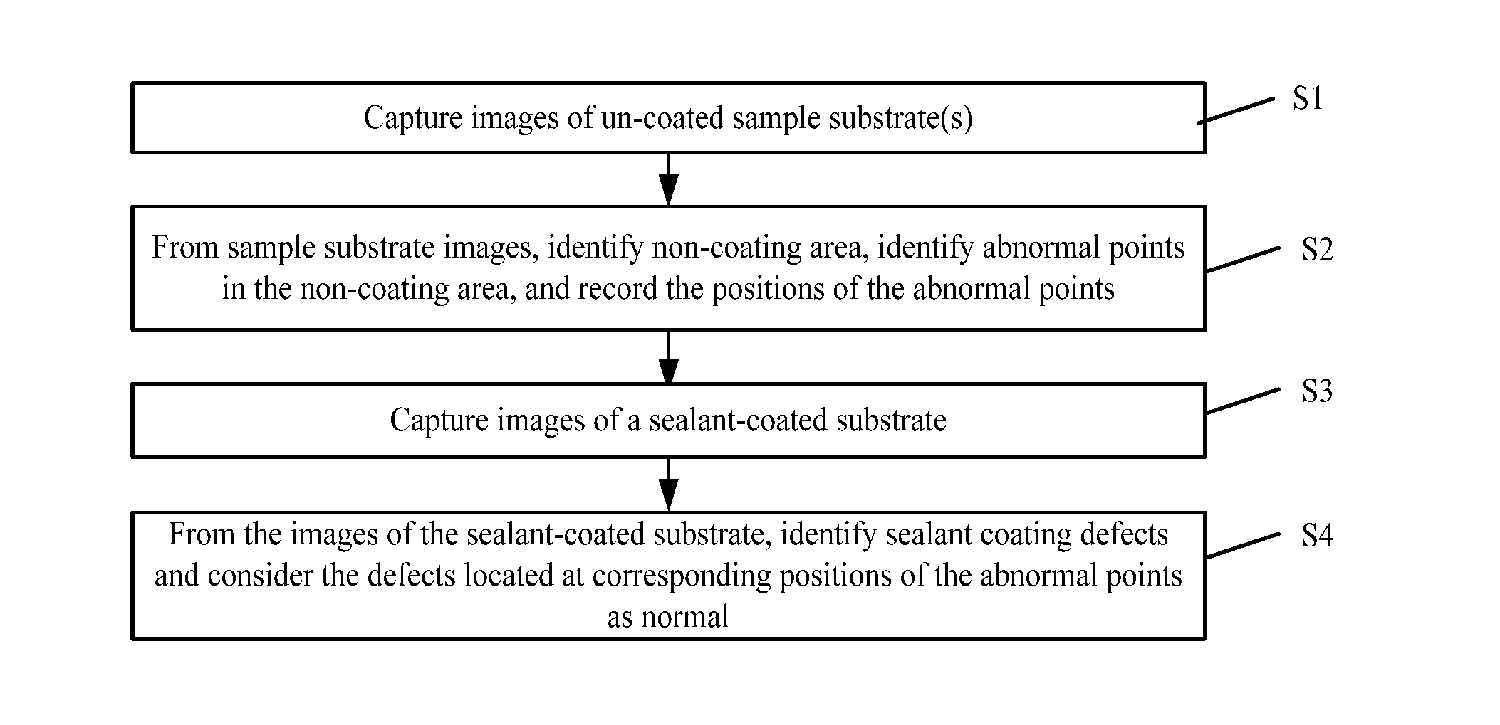
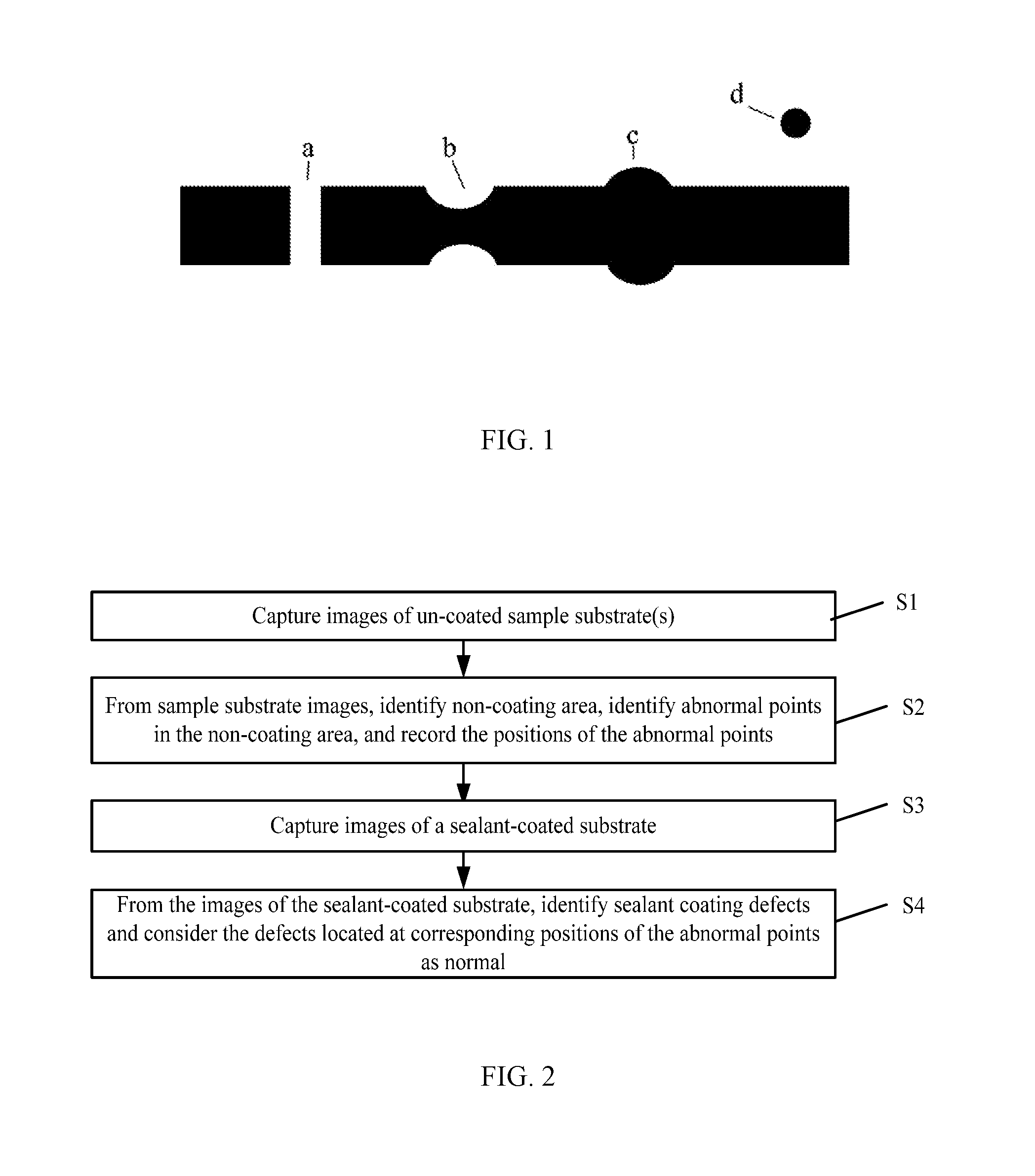
[0032]FIG. 2 illustrates a flow chart of an exemplary method of inspecting the sealant coating according to an exemplary embodiment of the present disclosure. In one embodiment, the inspection method is used to detect defects of sealant coating on the substrate. The method includes the following exemplary steps.

[...


PUM

PropertyMeasurementUnit
areaaaaaaaaaaa
brightnessaaaaaaaaaa
light intensityaaaaaaaaaa

Abstract

The present disclosure provides a method and a device of inspecting a sealant coating on a substrate. An image of a sample substrate is captured. The sample substrate is selected from a plurality of substrates. A non-coating area is identified from the image of the sample substrate. Abnormal points are identified in the non-coating area. Positions of the abnormal points are recorded. An image of a sealant-coated substrate having a sealant coating on one of the plurality of substrates is captured. Defect positions of the sealant coating are identified from the image of the sealant-coated substrate. Defects located in a non-coating area of the sealant-coated substrate at positions corresponding to the positions of the abnormal points identified based on the sample substrate are considered as normal.

Description

CROSS-REFERENCES TO RELATED APPLICATIONS[0001]This application claims the priority of Chinese patent application No. CN201410746965.5, filed on Dec. 8, 2014, the entire content of which is incorporated herein by reference.FIELD OF THE DISCLOSURE[0002]The present disclosure generally relates to the field of display technologies and, more particularly, relates to a sealant coating inspection method and a device thereof.BACKGROUND[0003]In making of a liquid crystal display (LCD) device, sealant materials are often coated and cured in the periphery of an array substrate or a color filter substrate. The sealant material is used to bond the array substrate and the color filter substrate together and to protect the liquid crystals injected into the space between the array substrate and the color filter substrate from being affected by the ambient air and water.[0004]After the array substrate or the color filter substrate is coated with the sealant material, the sealant coating needs to be ...

Claims


Application Information

Patent Timeline
Patent Type & Authority Applications(United States)
IPC IPC(8): G06T7/00G01N21/84H04N5/372G06K9/46H04N5/225G01N21/88G06K9/62
CPCG06T7/0004G01N21/8851G01N21/8422G06K9/6267G06T2207/30121H04N5/2256H04N5/372G01N2021/8887G01N2021/8433G06K9/4661G01N21/84G01N2021/8427G01N2021/9513G06F18/24H04N23/56H04N25/71
Inventor JING, YANGKUNDING, JIACHE, XIAOPANLI, HAIBO
Owner BOE TECH GRP CO LTD
Why Eureka
Try Eureka