
Unmanned aerial rescue system

a rescue system and unmanned technology, applied in the direction of energy-saving board measures, launching weapons, transportation and packaging, etc., can solve the problems of requiring maintenance and operation personnel, high acquisition cost, and high operating cost of traditional aerial vehicles, such as helicopters, airplanes,

Active Publication Date: 2016-12-08
CHAPPELL DANA R
View PDF16 Cites 39 Cited by
  • Summary
  • Abstract
  • Description
  • Claims
  • Application Information

AI Technical Summary

Benefits of technology

The patent describes an unmanned aerial system that includes a frame, landing members, a propulsion system, and a sensor system. The system also includes a sealed equipment container for holding a power source and control system, a parabolic shroud, a light system, a sound system, and a data communication system. The system can also have a propulsion system shield, a rescue equipment carrier, and a rescue equipment release mechanism. The technical effects of the patent include improved control and efficiency of the unmanned aerial system, as well as improved safety and reliability for use in rescue operations.

Problems solved by technology

However, traditional aerial vehicles, such as helicopters, airplanes, and the like, are expensive to acquire, expensive to operate, require personnel for both maintenance and operation, and generally require special bases for deployment.
This problem is even more remote for most airplanes because of the special equipment needed to launch and recover airplanes on the water.
Moreover, the use of traditional aerial vehicles, such as airplanes and helicopters, poses risk to rescue personnel, particularly where the vehicle needs to go into inclement conditions, such as inclement weather or dangerous terrain (e.g. mountains).
In some cases, the risk to the personnel and the equipment (given its high cost) is too substantial to deploy a rescue vehicle.
Until recently, alternatives to traditional aerial vehicles were not readily available to or not practical for search and rescue personnel.
However, unmanned aerial vehicles (UAVs), also known as unmanned aerial systems (UASs), have become increasingly prominent and sophisticated.

Method used


Image

  • Unmanned aerial rescue system
  • Unmanned aerial rescue system
  • Unmanned aerial rescue system

Examples


Embodiment Construction

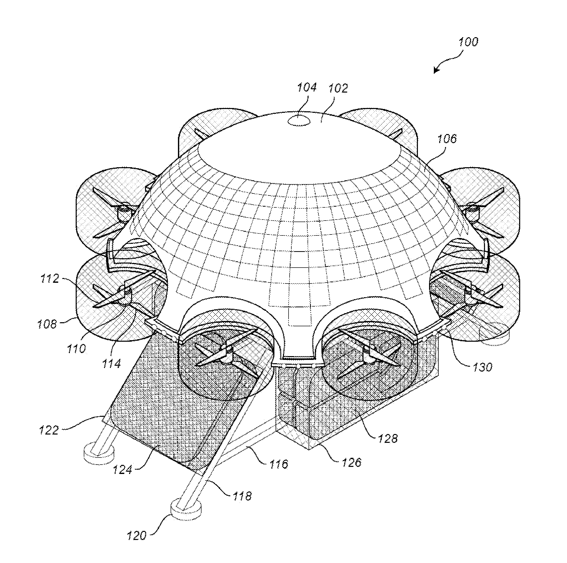
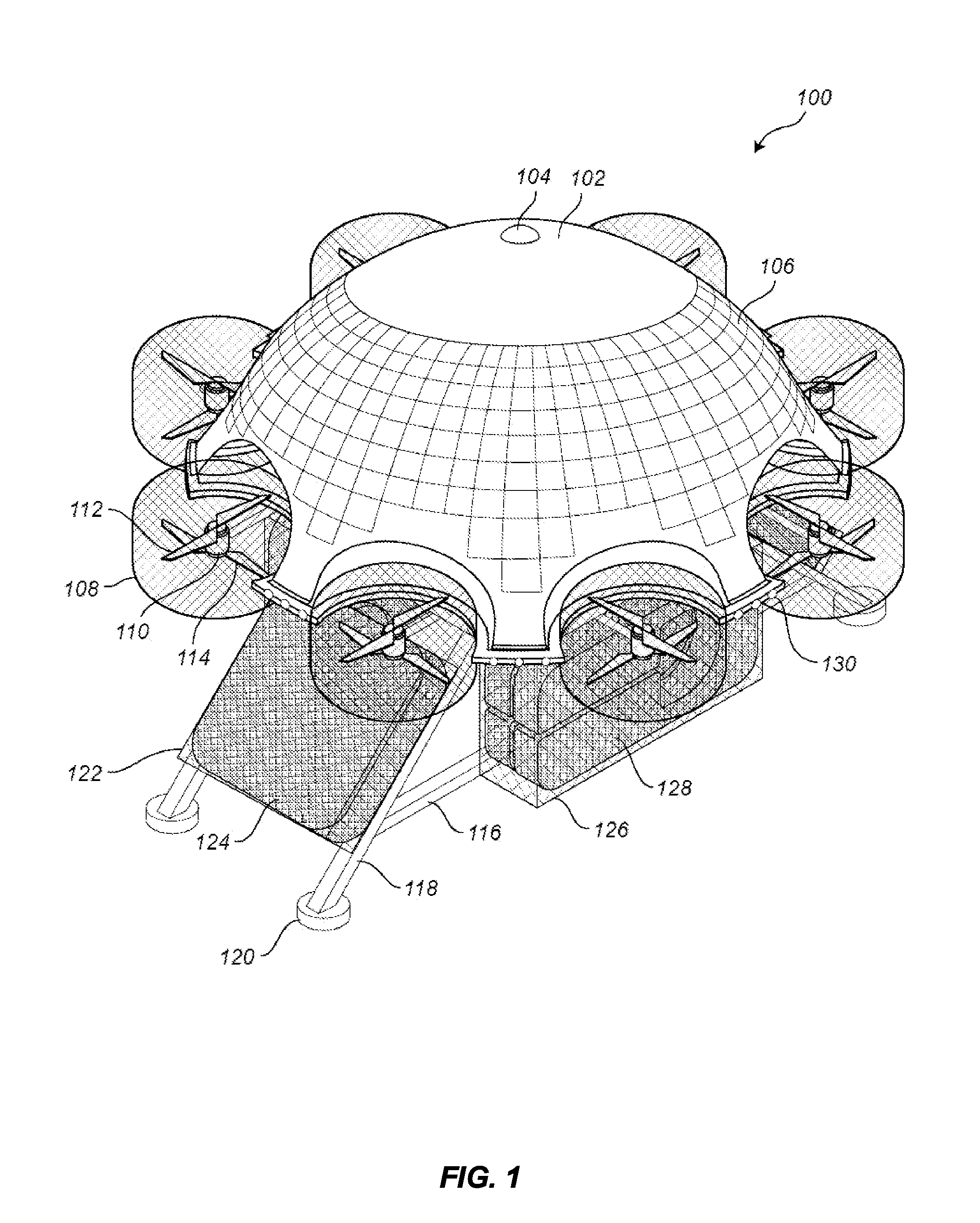
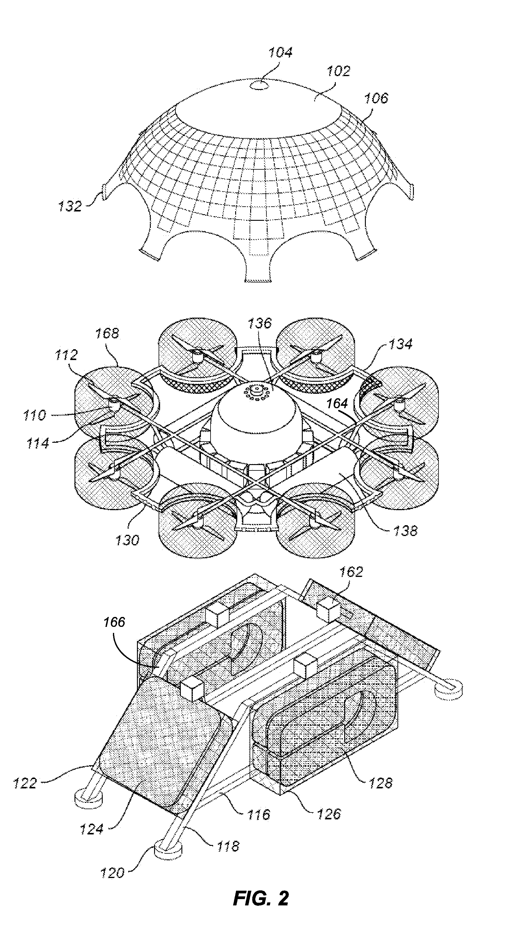
[0030]Embodiments disclosed in this application relate to unmanned aerial rescue systems. Generally speaking, unmanned aerial rescue systems are remotely or autonomously controlled flying vehicles or platforms capable of providing and deploying different forms of rescue equipment and assistance to individuals in need of assistance.

[0031]Embodiments of unmanned aerial rescue systems may comprise several components, including, for example: a frame or chassis, a landing member (e.g. landing leg), a control system, a propulsion system (e.g. a motor and propeller assembly), a propulsion system support member (e.g. a frame extension arm), a propulsion system orientation mechanism (e.g. a gimbal), a propulsion system shield (e.g. a mesh rotor shield), a sealed equipment container, a cover or shroud, an equipment carrier, an equipment release mechanism, a navigation system, a sensor system, a sound system, a light system, a data communication system, an emergency equipment system, and a pow...


PUM


Abstract

Embodiments of unmanned aerial rescue systems are disclosed, which may comprise: a frame or chassis, a landing member, a control system, a propulsion system, a propulsion system support member, a propulsion system orientation mechanism, a rotor shield or protector, a sealed equipment container, a cover or shroud, an equipment carrier, an equipment release mechanism, a navigation system, a sensor system, a sound system, a light system, a data communication system, an emergency equipment system, and a power management system. In some embodiments, a parabolic shroud increases the performance of sensor systems of the unmanned aerial rescue system, such as sound and light systems.

Description

BACKGROUND OF THE INVENTION[0001]Aerial vehicles, such as airplanes and helicopters, have traditionally been the vehicles of choice for search and rescue operations. In particular, aerial vehicles are often best suited for rescue operations conducted over vast and rugged terrain as well as over water because aerial vehicles may cover vast distances quickly using advanced instruments to search for and provide rescue services to those in need.[0002]However, traditional aerial vehicles, such as helicopters, airplanes, and the like, are expensive to acquire, expensive to operate, require personnel for both maintenance and operation, and generally require special bases for deployment. For example, a helicopter cannot be deployed from just any ship at sea, it must be deployed from a ship designed for helicopter operations. This problem is even more remote for most airplanes because of the special equipment needed to launch and recover airplanes on the water. Moreover, the use of tradition...

Claims


Application Information

Patent Timeline
Patent Type & Authority Applications(United States)
IPC IPC(8): B64C39/02B64D47/08B64D47/06B60Q5/00B64C27/52B64D1/10
CPCB64C39/024B64C27/52B64D1/10B64D47/06B60Q5/00B64C2201/108B64D2211/00B64C2201/024B64C2201/042B64C2201/127B64D47/08Y02T50/50B64U50/19B64U2101/30B64U30/26B64U10/16B64U2101/55B64U20/90B64U50/38B64D27/353B64U2201/20B64U2201/10
Inventor CHAPPELL, DANA R.
Owner CHAPPELL DANA R
Learn More