
Key cylinder release mechanism for vehicle closure latches, latch assembly therewith and method of mechanically releasing a vehicle closure latch

a technology of key cylinder and release mechanism, which is applied in the direction of passenger lock actuation, electrical locking circuit, lock application, etc., can solve the problems of relative movement between the key cylinder and the power latch assembly, failure of the vehicle's main power supply, interruption or breakage of electrical connections, etc., to facilitate the movement of the release link

Active Publication Date: 2016-12-15
MAGNA CLOSURES INC
View PDF0 Cites 21 Cited by
  • Summary
  • Abstract
  • Description
  • Claims
  • Application Information

AI Technical Summary

Benefits of technology

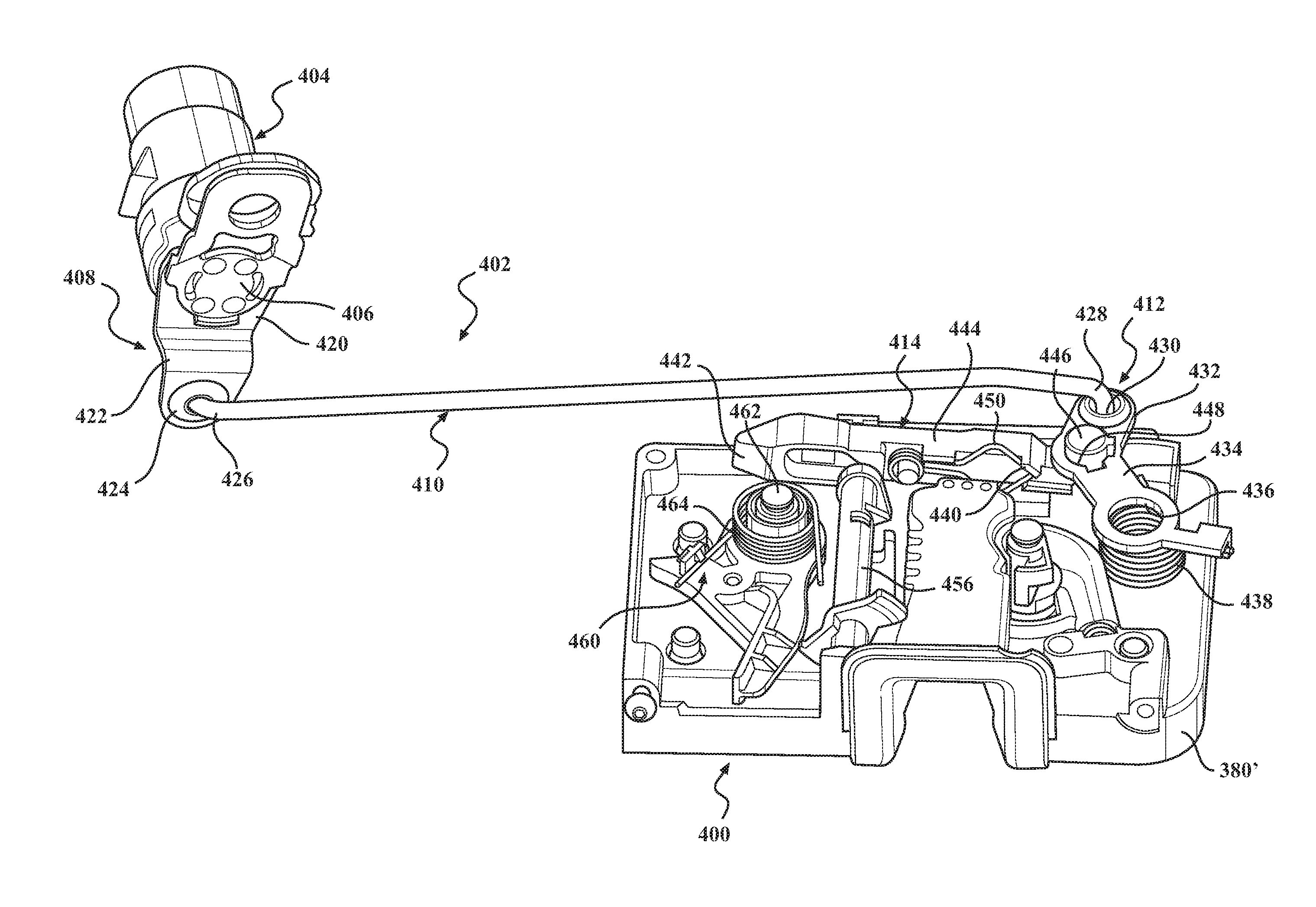
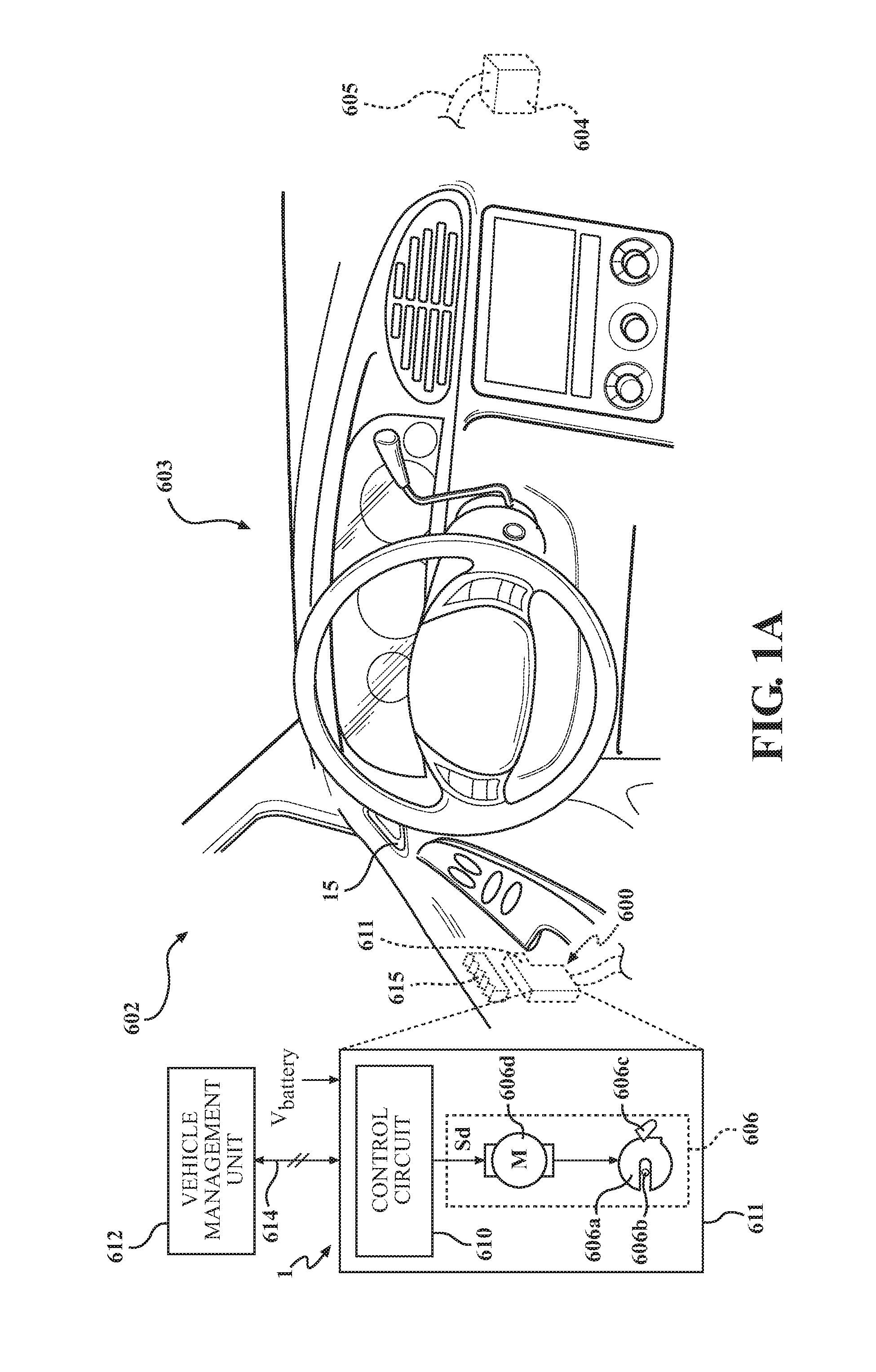
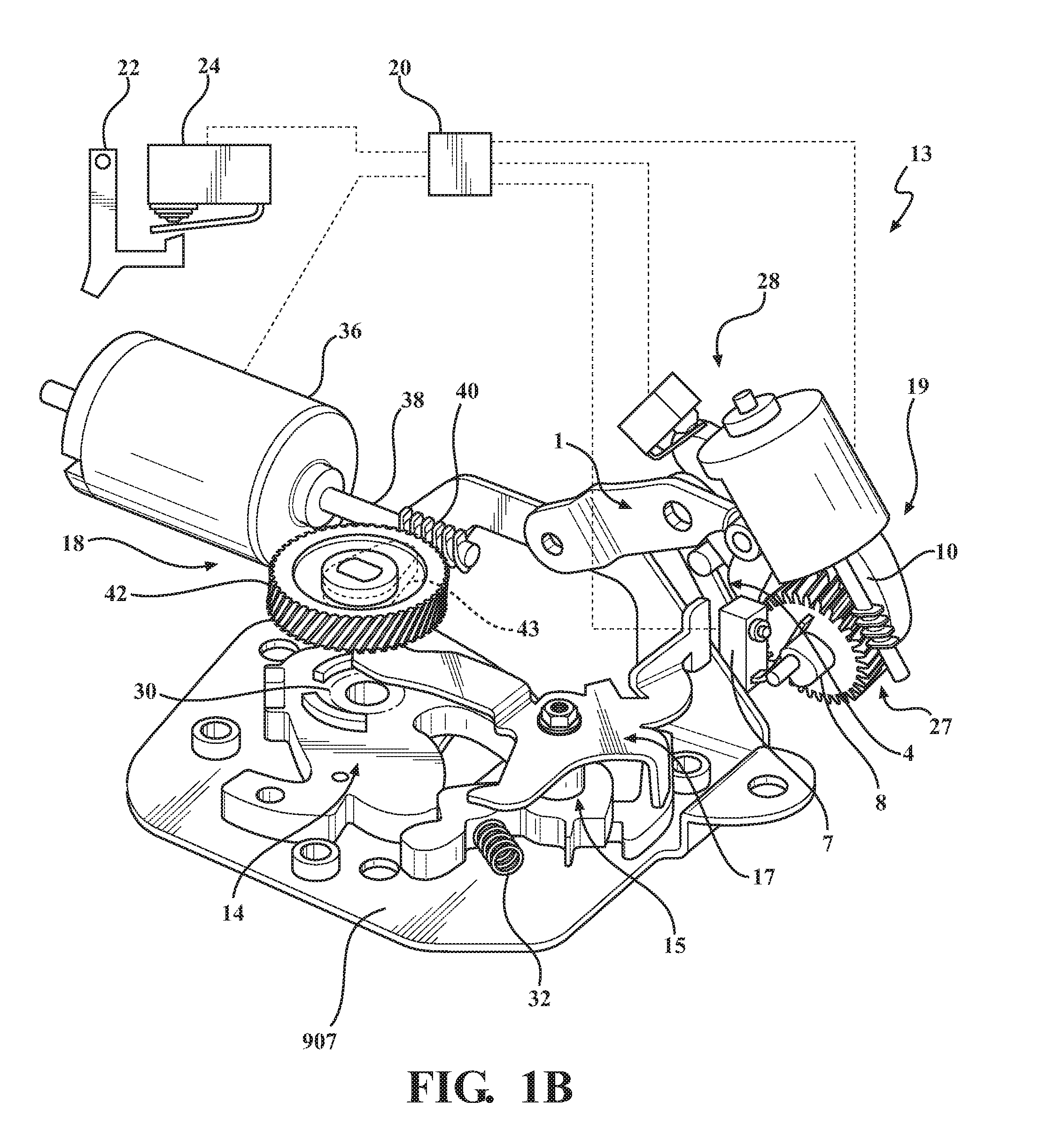
This patent describes a power latch assembly for a motor vehicle closure system that provides both a power release and a mechanical release feature. The assembly includes a ratchet, pawl, and latch release mechanism. The latch release mechanism can be activated using a key cylinder release mechanism that requires at least two distinct movements or actions to move the release link between a lock position and an unlock position. The power-operated actuation mechanism shifts the latch release mechanism between a latch lock mode and a latch release mode. The invention provides a more complex and reliable mechanism for unlatching the power-operated latch, ensuring safe and secure use of the motor vehicle closure system.

Problems solved by technology

However, during such an emergency situation, failure of the vehicle's main power supply, or interruptions or breaking of the electrical connections between the main power supply and / or the crash management controller and the power latch assembly may occur.
One drawback associated with conventional mechanical release systems is that relative movement between the key cylinder and the power latch assembly may occur during the crash event.

Method used


Image

  • Key cylinder release mechanism for vehicle closure latches, latch assembly therewith and method of mechanically releasing a vehicle closure latch
  • Key cylinder release mechanism for vehicle closure latches, latch assembly therewith and method of mechanically releasing a vehicle closure latch
  • Key cylinder release mechanism for vehicle closure latches, latch assembly therewith and method of mechanically releasing a vehicle closure latch

Examples


Embodiment Construction

[0044]Example embodiments will now be described more fully with reference to the accompanying drawings. Example embodiments are provided so that this disclosure will be thorough, and will fully convey the scope to those who are skilled in the art. Numerous specific details are set forth such as examples of specific components, devices, and methods, to provide a thorough understanding of embodiments of the present disclosure. It will be apparent to those skilled in the art that specific details need not be employed, that example embodiments may be embodied in many different forms and that neither should be construed to limit the scope of the disclosure. In some example embodiments, well-known processes, well-known device structures, and well-known technologies are not described in detail.

[0045]The terminology used herein is for the purpose of describing particular example embodiments only and is not intended to be limiting. As used herein, the singular forms “a,”“an,” and “the” may b...


PUM


Abstract

A power latch assembly is disclosed having a latch mechanism, a power release mechanism for selectively releasing the latch mechanism using an electric actuator, and a key cylinder mechanical release mechanism configured to release the latch mechanism in response to two distinct user input activation movements.

Description

CROSS-REFERENCE TO RELATED APPLICATION[0001]This application claims the benefit of U.S. Provisional Application Ser. No. 62 / 174,152, filed Jun. 11, 2015, which is incorporated herein by reference in its entirety.FIELD OF THE INVENTION[0002]The present disclosure relates generally to closure latches for motor vehicles and, more particularly, to a power latch assembly equipped with key cylinder release mechanism configured to require at least two actuation inputs to permit mechanical release of the latch mechanism.BACKGROUND OF THE INVENTION[0003]This section provides background information related to the disclosure that is not necessarily prior art.[0004]In the following description, the expression “closure panels” will be used to generally indicate any component or element moveable between an open position and a closed position, respectively opening and closing an access to an inner compartment of a motor vehicle. As such, the term closure member shall include, without limitation, r...

Claims


Application Information

Patent Timeline
IPC IPC(8): E05B81/90E05B81/76E05B85/24E05B83/36E05B79/16E05B81/06E05B81/16E05B85/06E05B81/56E05B85/26
CPCE05B81/90E05B81/56E05B81/76E05B81/77E05B85/243E05B83/36E05B79/16E05B81/06E05B81/16E05B85/06E05B85/26E05B77/26E05B77/265E05B77/32E05B81/14E05B81/34E05B81/42E05B81/72E05B81/78E05B85/01E05B77/28E05B77/30E05B81/64E05B81/74
Inventor TOMASZEWSKI, KRIS
Owner MAGNA CLOSURES INC
Learn More