Power transmission gearbox and an aircraft

a transmission gearbox and transmission gear technology, applied in the direction of gear lubrication/cooling, engine lubrication, rotocraft, etc., can solve the problems of deformation, heavy additional system, and needing permanent lubrication of the gearbox of the helicopter main, so as to improve the adaptability to mist generation

Active Publication Date: 2016-12-15
EUROCOPTER
View PDF0 Cites 18 Cited by
  • Summary
  • Abstract
  • Description
  • Claims
  • Application Information

AI Technical Summary

Benefits of technology

[0071]This second embodiment presents the advantage of making it possible to use a lubrication fluid that is different from the lubrication liquid. For example, the lubrication fluid and the lubrication liquid may comprise respective oils presenting different characteristics. Thus, the lubrication fluid may be an oil that is better adapted to mist generation and / or more effective at high temperature than the lubrication liquid.

Problems solved by technology

The sets of gears present in helicopter main gearboxes need to be lubricated permanently, possibly in degraded manner as a result of certain failures.
The additional system may be heavy and difficult to arrange in an environment that is encumbered by numerous members.

Method used


Image

  • Power transmission gearbox and an aircraft
  • Power transmission gearbox and an aircraft
  • Power transmission gearbox and an aircraft

Examples


first embodiment

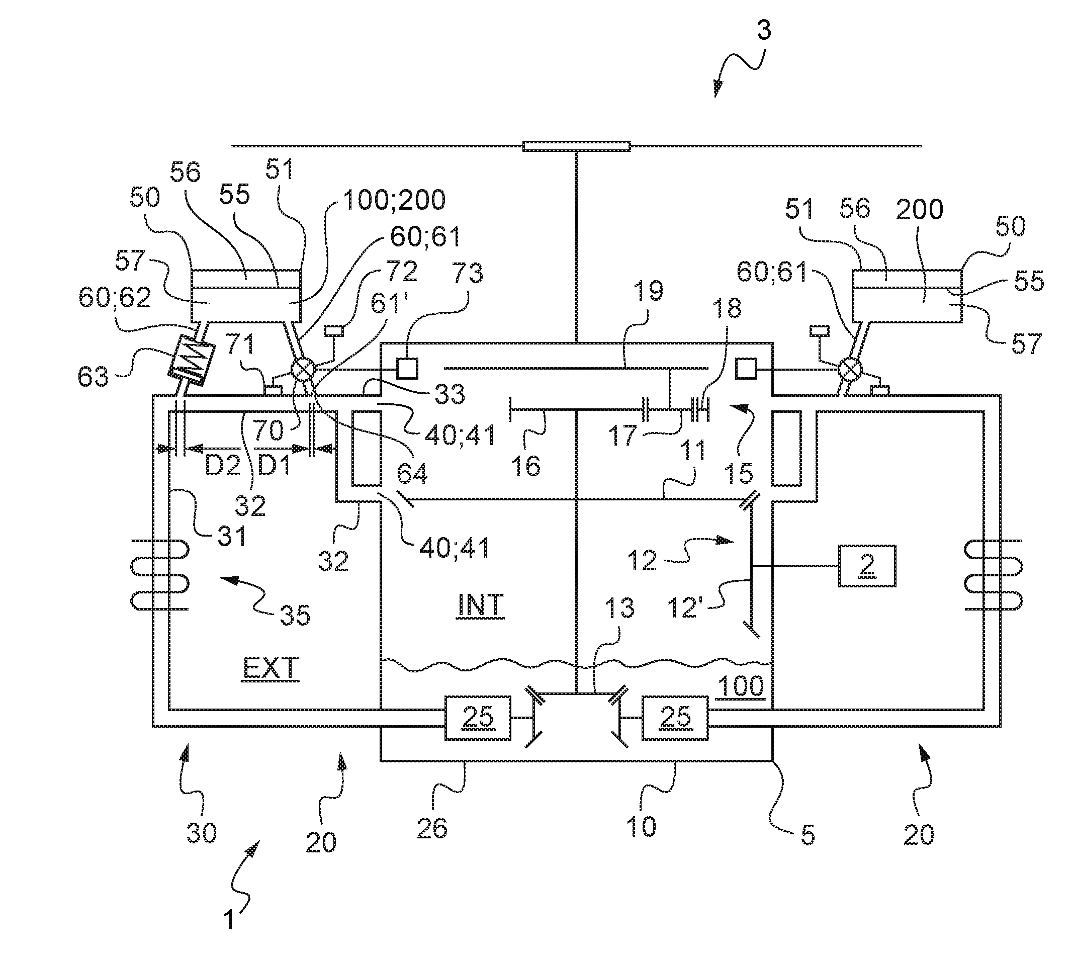
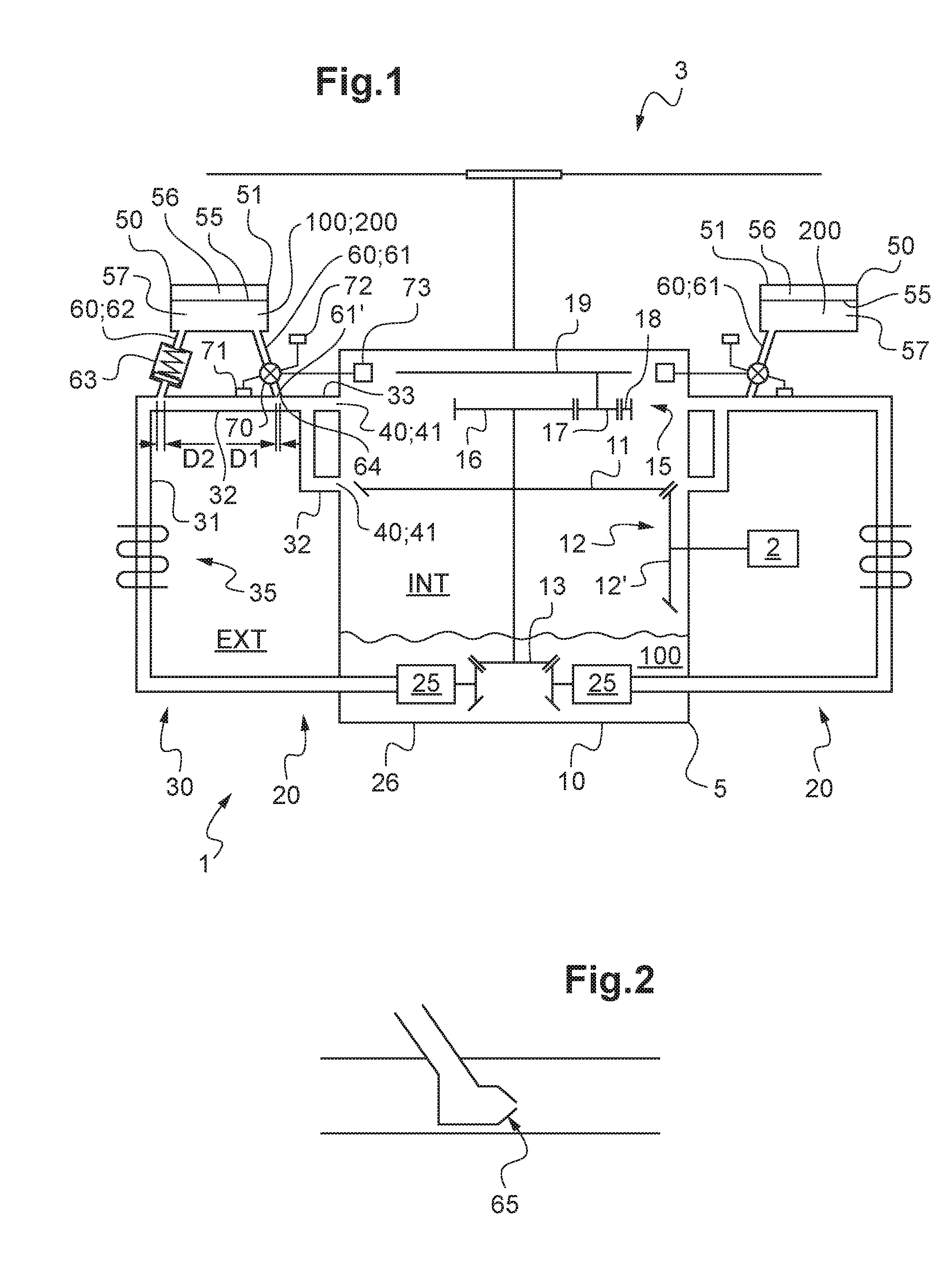
[0119]In a first embodiment illustrated by the lubrication system 20 shown on the left in FIG. 1, the emergency tank is filled by the fluid flow circuit 30.

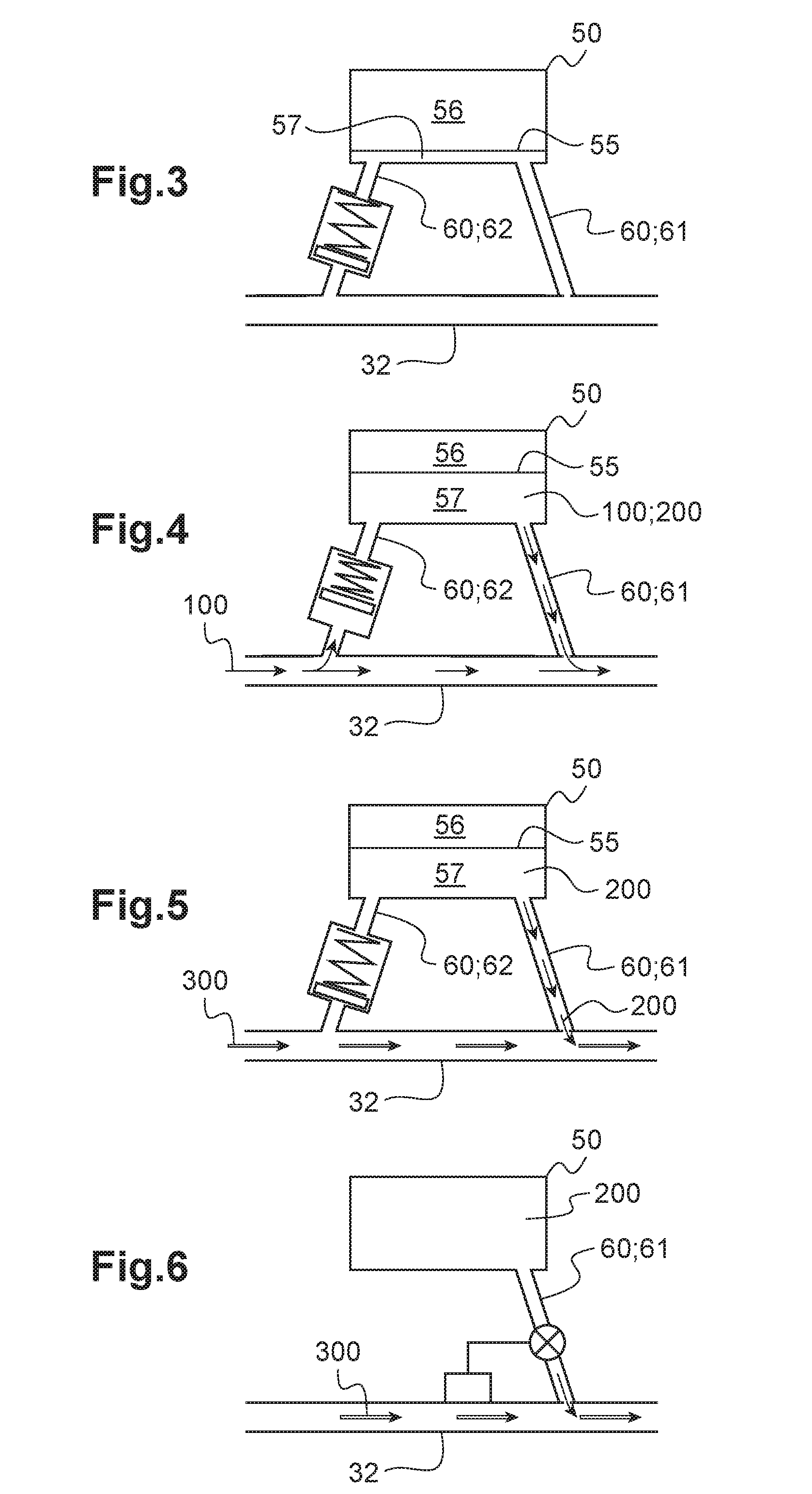
[0120]In the absence of a leak of lubrication liquid, a fraction of the lubrication liquid fills the emergency tank. The lubrication fluid 200 thus represents a fraction of the lubrication liquid 100.

[0121]The outlet pipe can enable the lubrication liquid to be conveyed to the emergency tank in a first alternative that is not shown.

[0122]Nevertheless, in a second alternative as shown in FIG. 1, the emergency tank includes an “inlet” pipe 62 in order to enable it to be filled by the fluid flow circuit.

[0123]The inlet pipe 62 is situated upstream from the outlet pipe 61. The inlet pipe also extends from the fluid flow circuit and, in particular, from the central duct 32, to the shell 51 of the emergency tank 50.

[0124]This inlet pipe 62 may be a one-way connection enabling lubrication liquid to flow solely from the fluid flow circui...

second embodiment

[0128]In a second embodiment illustrated by the lubrication system 20 arranged on the right in FIG. 1, the emergency tank is not filled by the fluid flow circuit 30.

[0129]The emergency tank 50 is connected to the fluid flow circuit 30 solely by an outlet pipe 61.

[0130]Furthermore, the lubrication fluid 200 is distinct from the lubrication liquid 100. The term “is distinct from the lubrication liquid 100” means that the lubrication fluid is not a portion of the lubrication liquid. The lubrication fluid is introduced into the emergency tank 50 by an operator.

[0131]Nevertheless, the lubrication fluid and the lubrication liquid may be fluids that are different or identical.

[0132]The outlet pipe may be provided with a valve of the type described above.

[0133]Independently of the way the emergency tank is embodied, the lubrication system does not have a compressor external to the gearbox.

[0134]Specifically, in the event of a leak of lubrication liquid, the lubrication fluid 200 contained i...


PUM


Abstract

A power transmission gearbox provided with at least one lubrication system including a lubrication pump. The lubrication pump is in fluid flow communication with a fluid flow circuit leading to at least one spray means. The gearbox includes an emergency tank suitable for containing a lubrication fluid, the emergency tank being in fluid flow communication with the fluid flow circuit, the emergency tank being connected by at least one pipe to the fluid flow circuit upstream from each spray means, the lubrication fluid being moved in the fluid flow circuit to each spray means by a gas that is set into motion by the lubrication pump in the event of a leak of the lubrication liquid.

Description

CROSS REFERENCE TO RELATED APPLICATION[0001]This application claims priority to French patent application No. FR 15 01213 filed on Jun. 11, 2015, the disclosure of which is incorporated in its entirety by reference herein.BACKGROUND OF THE INVENTION[0002](1) Field of the Invention[0003]The present invention relates to a power transmission gearbox, and also to an aircraft provided with such a gearbox.[0004]In particular, an aircraft of the rotorcraft type has a rotor that contributes to providing the aircraft with at least part of its lift. A rotorcraft of the helicopter type may thus have a “main” rotor for providing it with lift and with propulsion.[0005](2) Description of Related Art[0006]In order to set such a rotor into rotation, a rotorcraft is provided with a power plant including at least one engine.[0007]In addition, a gearbox may be interposed between the engines and a rotor in order to transmit the power developed by the engines to the rotor. A particular function of the g...

Claims


Application Information

Patent Timeline
Patent Type & Authority Applications(United States)
IPC IPC(8): F16H57/04B64D35/02
CPCF16H57/046B64D35/02F16H57/0442F16H57/0435B64C27/12F16H57/0434F16H57/045F16H57/0456B64D35/00F16N7/40F16N2260/24F16N2260/50F16H57/0436F16N2260/20
Inventor LOUIS, CHARLES
Owner EUROCOPTER
Why Eureka
Try Eureka