Network interface, network and method for data transmission within the network

a network interface and data transmission technology, applied in digital transmission, data switching by path configuration, electrical equipment, etc., can solve the problems of high installation cost, low adaptability, complex wiring with a multiplicity of required plug connections and data lines, etc., to enable latency-period-optimised and reliable communication, reliable network operation, and transmit reliably and fast

Active Publication Date: 2016-12-15
AIRBUS DEFENCE & SPACE
View PDF14 Cites 2 Cited by
  • Summary
  • Abstract
  • Description
  • Claims
  • Application Information

AI Technical Summary

Benefits of technology

[0035]When the transfer of the defect detection reaches the server network user, then the server network user can confirm this information and send the data signal in the series of network users, which can trigger the reversal of the data direction within each network user downstream of the defect location. Alternatively, the client network users, which have detected a defect, can also reverse their data directions after a certain wait time. Thereafter, the server can send data in both directions of the network ring, so that the reliable operation of the network can be maintained to the greatest possible extent.
[0036]In summary, a network interface is presented here, which can forward data within a network without a latency period, particularly in the case of downlinks. The network itself can additionally make use of the advantages that the network users can be constructed identically to the greatest extent possible, in terms of hardware, and data can be transmitted reliably and fast, also by means of the methods described here. Defects can be detected reliably and in good time and the communication can nonetheless be maintained within the network. Thus, a technical option is described here for enabling latency-period-optimised and reliable communication.

Problems solved by technology

These requirements often lead to complex wiring with a multiplicity of required plug connections and data lines, e.g. in the case of a star architecture.
Disadvantages arise here due to the associated high weight, the high installation outlay and the low adaptability.
However, these architectures have high latency as a disadvantage, such as the HSR (high-availability seamless redundancy) standard.

Method used


Image

  • Network interface, network and method for data transmission within the network
  • Network interface, network and method for data transmission within the network
  • Network interface, network and method for data transmission within the network

Examples


Embodiment Construction

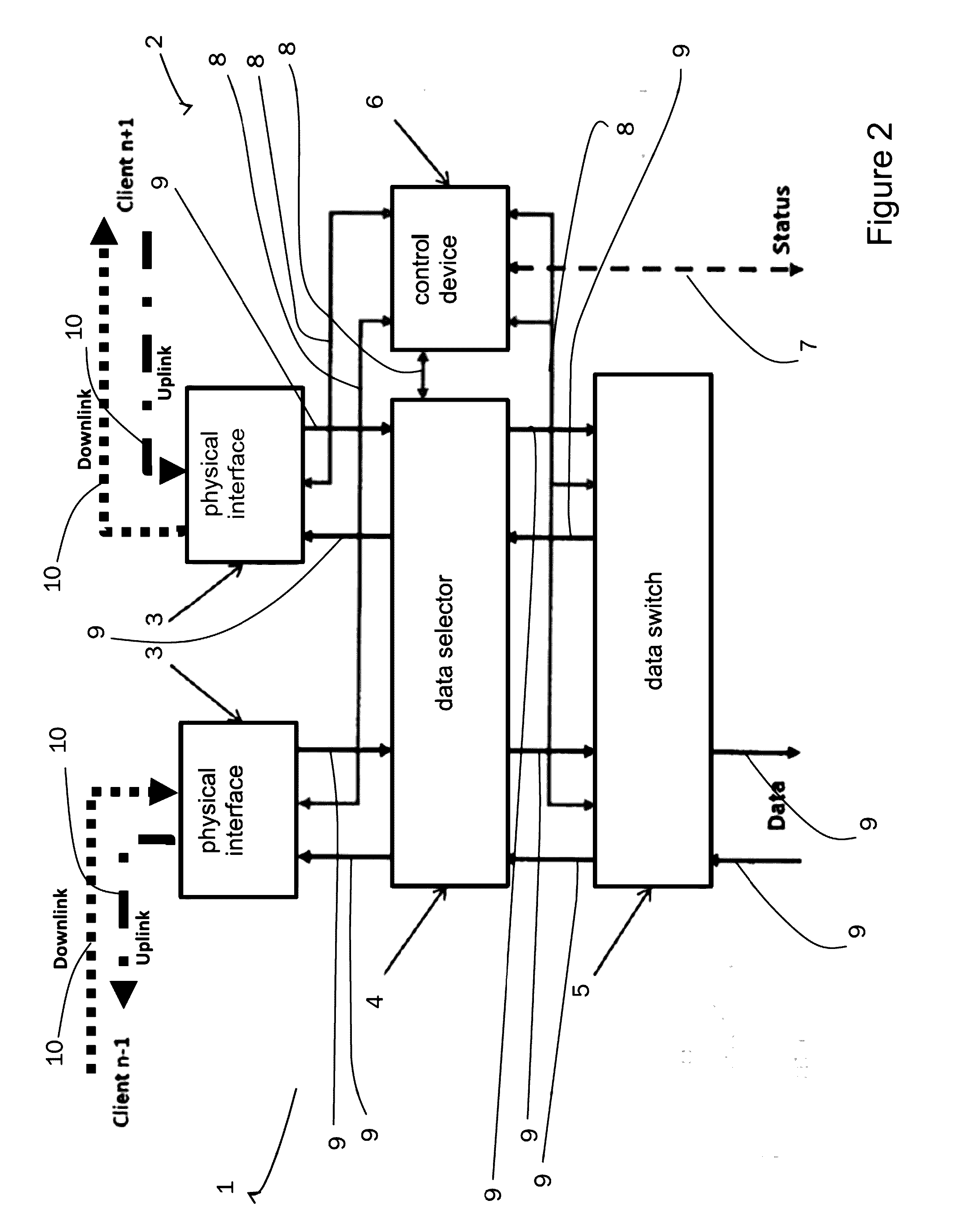
[0046]Various examples are described in detail and with reference to the figures in the following. Identical or similar elements in the figures are designated with identical reference numbers. The present devices and methods are not limited to the described combinations of features however. Rather, further modifications and combinations of features of various examples should also be included in the context of the protective scope of the independent claims.

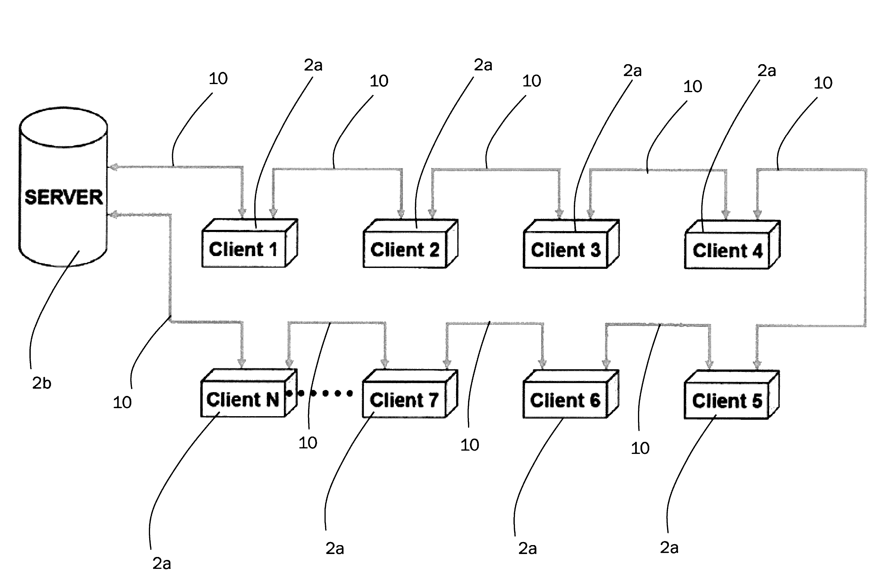
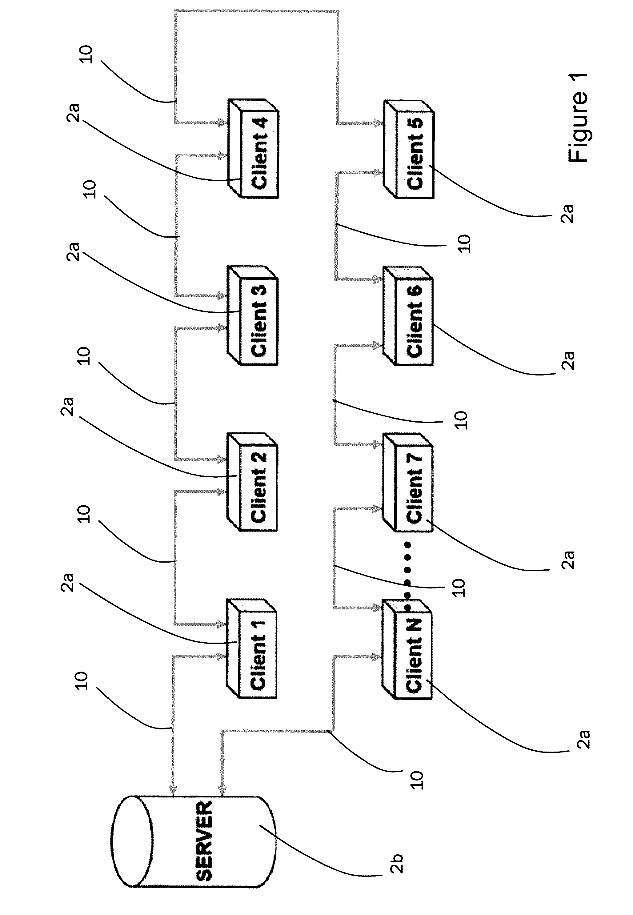
[0047]FIG. 1 shows a schematic design of a fault-tolerant, latency-period-optimised ring structure of a network described here. The client network users 2a (for short: client; client 1 to client N) are connected in series (daisy chain) to a server network user 2b (for short: server). Both the first “client 1” and the last “client N” are connected to the server 2b, so that a closed architecture, a ring, results.

[0048]The data connections are indicated in FIG. 1 with double arrows, from which it can be seen that a communication is po...


PUM


Abstract

A network interface of a network user having at least one physical interface for connecting the network interface to a network interface of a different network user, at least one data selector, which is connected to the physical interface and which is suitable for receiving data from the physical interface and sending data to the physical interface, and at least one data switch, which is connected to the data selector and which is suitable for receiving data from the data selector and sending data to the data selector.

Description

FIELD OF THE INVENTION[0001]The embodiments described herein relate in particular to a network interface of a network user having at least one physical interface for connecting the network interface to a network interface of a different network user, at least one data selector and at least one data switch. Furthermore, the application relates to a network, which has network users with the network interfaces mentioned, and also methods for data transmission and fault detection within the network. Technical advantages result from the fact that the network interface can transmit data within the network, particularly in the case of downlink connections, without or with a very low latency. The network itself can additionally make use of the technical advantages that the network users can be constructed identically to the greatest extent possible, with regards to the hardware, and data can be transmitted reliably and fast, also by means of the methods described here. Defects can be detect...

Claims


Application Information

Patent Timeline
Patent Type & Authority Applications(United States)
IPC IPC(8): H04L12/437H04L29/08
CPCH04L12/437H04L2012/421H04L67/12H04L12/42H04L2012/4028
Inventor PRUECKLMEIER, ANDREASPISTNER, THOMASSCHNEELE, STEFAN
Owner AIRBUS DEFENCE & SPACE
Why Eureka
Try Eureka