
Manifold for multiple compression drivers with a single point source exit

a compression driver and manifold technology, applied in the field of loudspeaker systems, can solve the problems of affecting the overall quality of the sound emanating from the manifold, affecting the overall sound of the manifold, so as to achieve the effect of reducing the fidelity and intelligibility of the overall sound, reducing the acoustic interference pattern, and reducing the sensitivity of the manifold

Active Publication Date: 2016-12-15
HARMAN INT IND INC
View PDF22 Cites 0 Cited by
  • Summary
  • Abstract
  • Description
  • Claims
  • Application Information

AI Technical Summary

Benefits of technology

The disclosed techniques allow loudspeakers to use compression drivers in a way that reduces comb filtering and acoustic interference that can damage sound quality and make it harder to hear. As a result, these loudspeakers generate high sound pressure levels without compromising sound quality.

Problems solved by technology

However, when two compression drivers emit sound waves, the sound waves may generate acoustical reflections and interference.
Such reflections and interference can lead to comb filtering (i.e., reinforcement of some sound waves and cancellation of other sound waves) and / or acoustic interference patterns that compromise the fidelity and intelligibility of the overall sound for the audience.
One drawback of this particular approach is that acoustic reflections and interference still persist within the manifold that can degrade the overall quality of the sound emanating from the manifold.
In particular, the interactions of the four sound waves within the manifold can produce artifacts, such as crossmodes, that remain present when the four waveforms are combined.
Those crossmodes and other similar artifacts degrade the quality of the sound ultimately produced via the manifold, which hinders the ability to produce high fidelity sound.
In general, conventional approaches to combining multiple compression drivers suffer similar sound degradation that is attributable to interference and / or reflections within the manifold.

Method used


Image

  • Manifold for multiple compression drivers with a single point source exit
  • Manifold for multiple compression drivers with a single point source exit
  • Manifold for multiple compression drivers with a single point source exit

Examples


Embodiment Construction

[0018]In the following description, numerous specific details are set forth to provide a more thorough understanding of the present invention. However, it will be apparent to one of skill in the art that the present invention may be practiced without one or more of these specific details.

Audio System

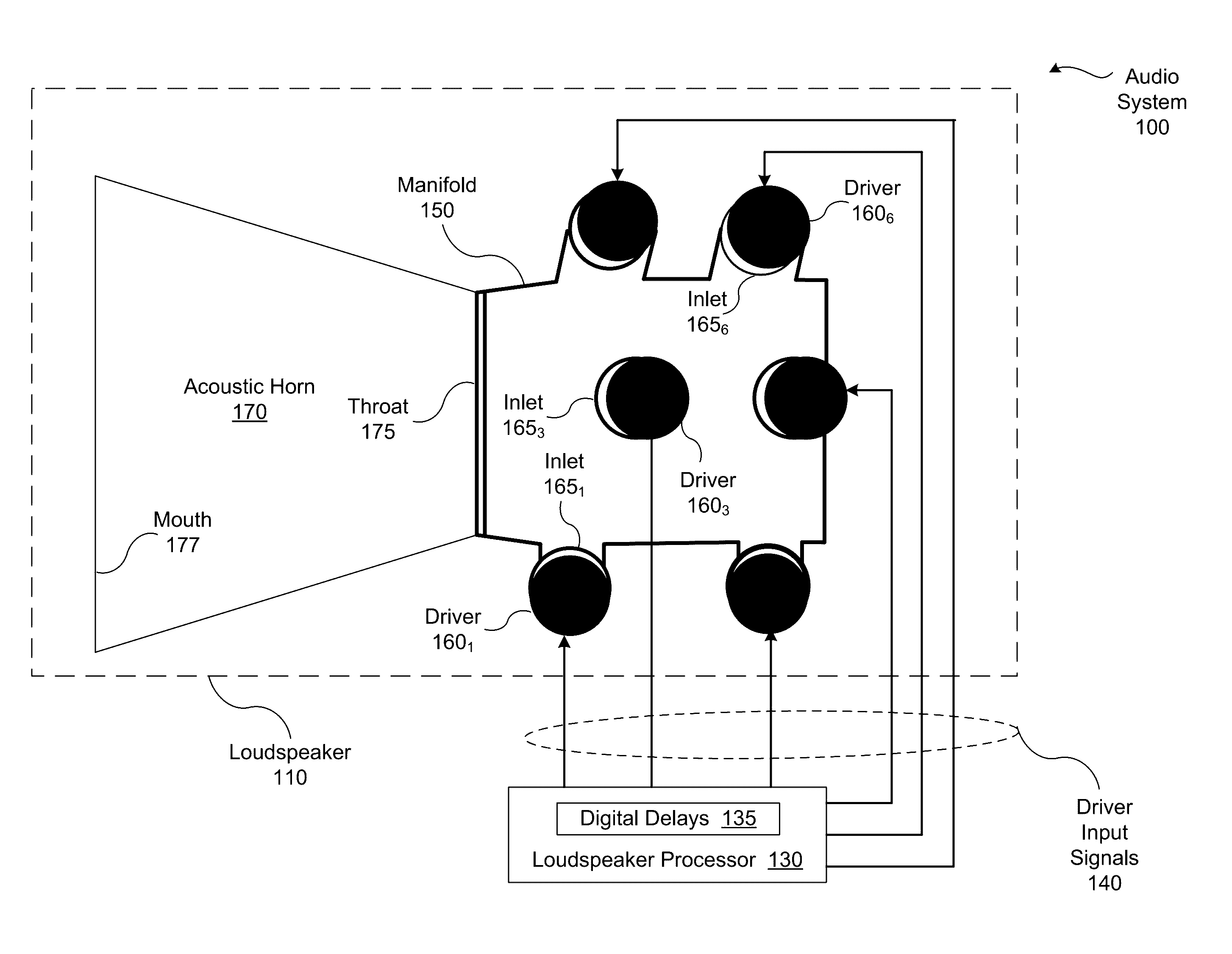
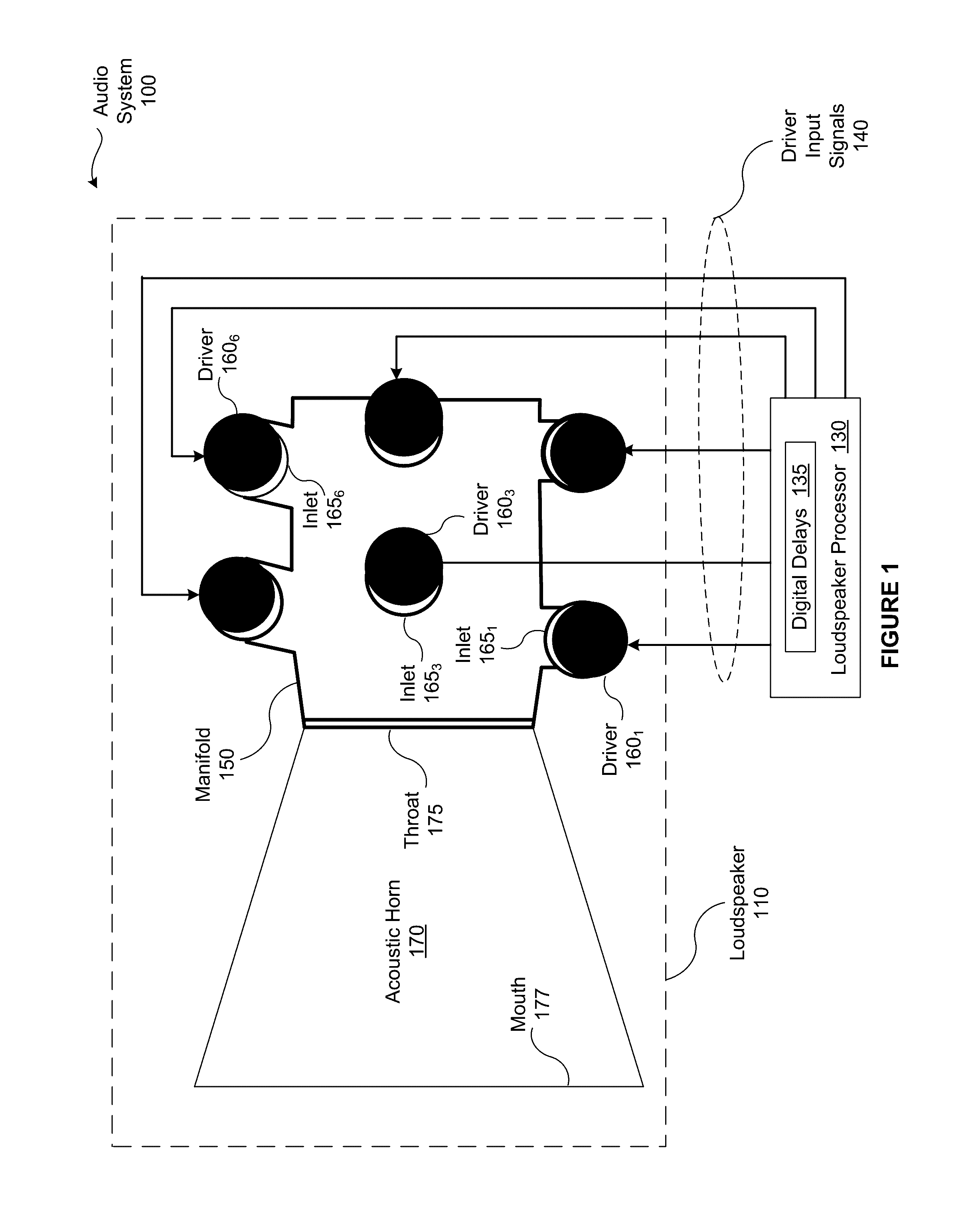
[0019]FIG. 1 illustrates an audio system 100 configured to implement one or more aspects of the various embodiments. As shown, the audio system 100 includes, without limitation, a loudspeaker 110 and a loudspeaker processor 130. In alternate embodiments, the audio system 100 may include any number of loudspeakers 110 and any number of loudspeaker processors 130. Further, the loudspeaker processor 130 may be integrated into the loudspeaker 110 or replaced with any other integrated or stand-alone control unit. In various embodiments, the audio system 100 may include any number and type of audio equipment in any combination.

[0020]The loudspeaker 110 is a “horn” loudspeaker that is designed ...


PUM


Abstract

In one embodiment of the present invention, a manifold composites sound from multiple drivers into a single aperture that includes multiple concentric rings. In operation, channels within the manifold isolate the sound generated by each driver from the sound generated by the other drivers. The channels within the manifold are intertwined to route the sound from each driver to a separate location in one of the multiple concentric rings. When the sound generated by each of the drivers is judiciously and deterministically delayed, the manifold generates a single point source of sound that may be fed into an acoustic horn. Notably, by isolating the sound generated by each driver, the manifold minimizes reflections and resonances that often degrade the sound fidelity of conventional horn loudspeakers. Consequently, the disclosed manifold enables an acoustic horn to project coherent sound for significantly longer distances than the acoustic horn would achieve using a conventional manifold.

Description

BACKGROUND[0001]Field of the Invention[0002]Embodiments of the present invention relate generally to loudspeaker systems and, more specifically, to a manifold for multiple compression drivers with a single point source exit.[0003]Description of the Related Art[0004]Multiple compression drivers are commonly used to drive acoustic horns in loudspeakers that are designed to project sound for relatively long distances. For example, a loudspeaker in a public address system that is capable of projecting sound for hundreds of feet would typically include numerous compression drivers. However, when two compression drivers emit sound waves, the sound waves may generate acoustical reflections and interference. Such reflections and interference can lead to comb filtering (i.e., reinforcement of some sound waves and cancellation of other sound waves) and / or acoustic interference patterns that compromise the fidelity and intelligibility of the overall sound for the audience.[0005]In an effort to...

Claims


Application Information

Patent Timeline
Patent Type & Authority Applications(United States)
IPC IPC(8): H04R1/28
CPCH04R1/2865H04R1/30H04R9/063H04R27/00H04R2400/13
Inventor BUTTON, DOUGLAS J.
Owner HARMAN INT IND INC
Features
  • Generate Ideas
  • Intellectual Property
  • Life Sciences
  • Materials
  • Tech Scout
  • Unparalleled Data Quality
  • Higher Quality Content
  • 60% Fewer Hallucinations
Learn More