
Polymer composite piezoelectric body, electroacoustic transduction film, and electroacoustic transducer

Active Publication Date: 2017-12-28
FUJIFILM CORP
View PDF0 Cites 9 Cited by
  • Summary
  • Abstract
  • Description
  • Claims
  • Application Information

AI Technical Summary

Benefits of technology

The present invention provides a polymer composite piezoelectric body that can improve the conversion efficiency between electricity and sound, resulting in an increased sound pressure level. This is achieved by using a viscoelastic matrix containing polymer material with a cyanoethyl group, and by dispersing piezoelectric body particles and dielectric particles in the matrix. The piezoelectric body particles have an average particle diameter of more than or equal to 2.5 μm, and the dielectric particles have an average particle diameter of less than or equal to 0.5 μm and a relative permittivity of more than or equal to 80. This invention allows for a more efficient piezoelectric film that can produce better sound quality.

Problems solved by technology

However, when the volume fraction of the piezoelectric body particles in the piezoelectric layer is increased, the flexibility decreases, the interfacial peeling between the piezoelectric body particles and the binder occurs due to the vibration during driving and bending of the piezoelectric film, voids are formed, the interfacial peeling between the piezoelectric body particles and the binder occurs due to the vibration during driving and bending of the piezoelectric film, voids are formed, and the dielectric constant of the piezoelectric layer decreases.
Also, there is a limit to increasing the dielectric constant of the binder itself due to the selectivity of a material that is able to be used as the binder.

Method used


Image

  • Polymer composite piezoelectric body, electroacoustic transduction film, and electroacoustic transducer
  • Polymer composite piezoelectric body, electroacoustic transduction film, and electroacoustic transducer
  • Polymer composite piezoelectric body, electroacoustic transduction film, and electroacoustic transducer

Examples


example 1

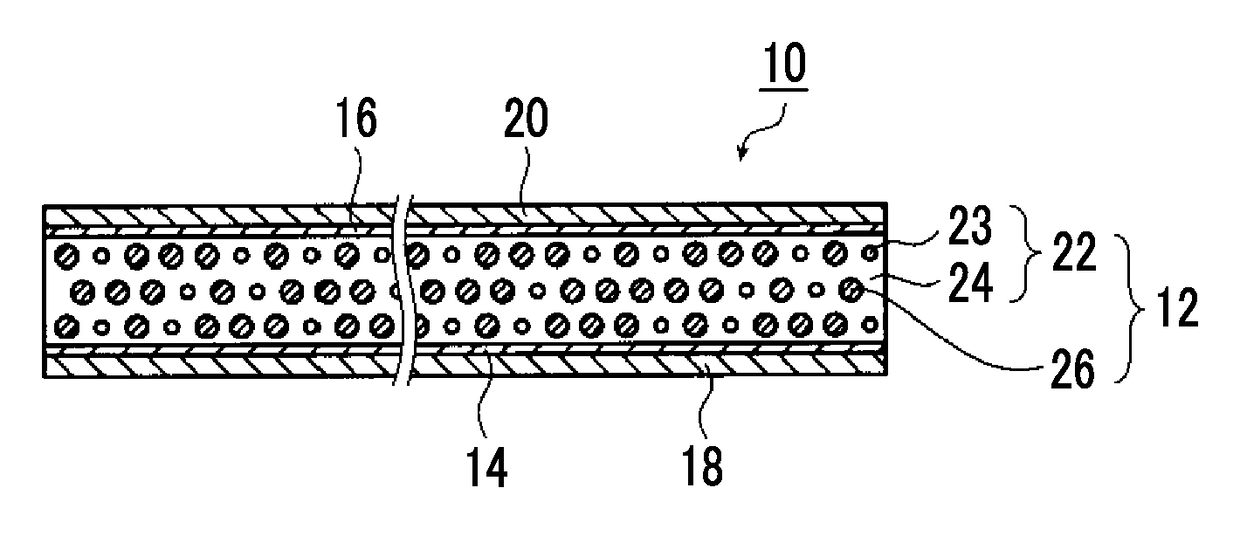
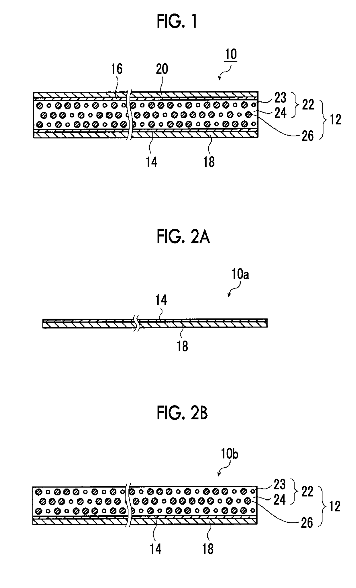
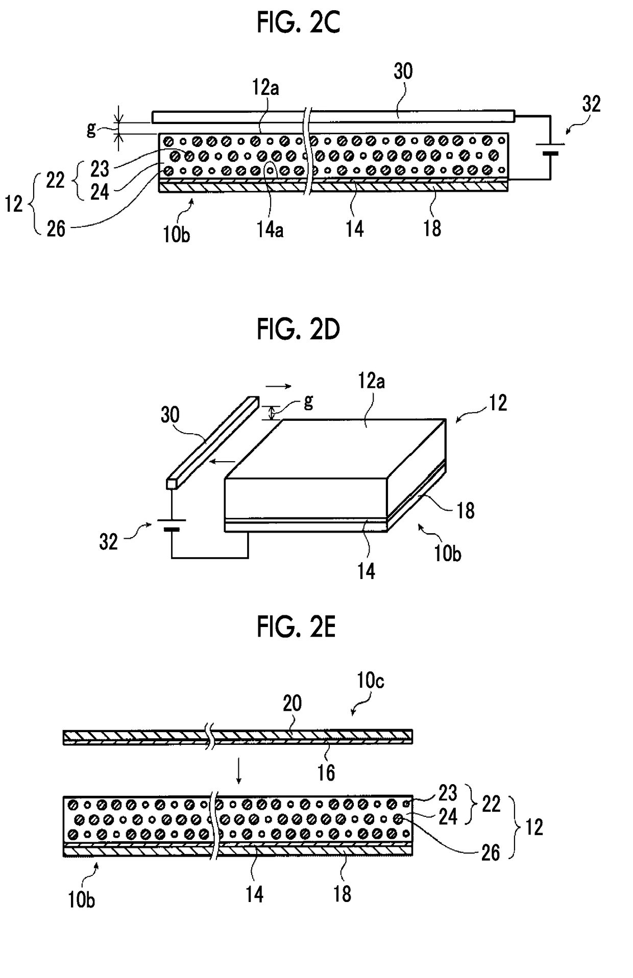
[0240]According to the method illustrated in FIGS. 2A to 2E described above, the transduction film 10 illustrated in FIG. 1 was prepared.

[0241]First, cyanoethylated PVA (CR-V manufactured by Shin-Etsu Chemical Co., Ltd.) was dissolved in methyl ethyl ketone (MEK) at the following compositional ratio. Thereafter, barium titanate (BaTiO3) as the dielectric particles and PZT particles as the piezoelectric body particles were added to this solution at the following compositional ratios, and were dispersed by using a propeller mixer (rotation speed 2000 rpm), and thus a coating material for forming the piezoelectric layer 12 was prepared.

PZT Particles1000 parts by mass BaTiO3 particles90 parts by massCyanoethylated PVA85 parts by massMEK567 parts by mass

[0242]In addition, as the PZT particles, those obtained by sintering commercially available PZT raw material powder at 1000° C. to 1200° C. and thereafter crushing and classifying the resultant so as to have an average particle diameter ...

example 2

[0257]An electroacoustic transducer was prepared in the same manner as in Example 1 except that the thickness of the piezoelectric layer 12 was set to 25 μm.

example 3

[0258]An electroacoustic transducer was prepared in the same manner as in Example 1 except that the thickness of the piezoelectric layer 12 was set to 20 μm.


PUM


Abstract

Provided are a polymer composite piezoelectric body in which the conversion efficiency between electricity and sound is increased and thus the sound pressure level is improved, an electroacoustic transduction film, and an electroacoustic transducer. The polymer composite piezoelectric body includes a viscoelastic matrix formed of a polymer material having a cyanoethyl group, piezoelectric body particles which are dispersed in the viscoelastic matrix and have an average particle diameter of more than or equal to 2.5 μm, and dielectric particles dispersed in the viscoelastic matrix, in which the dielectric particles are formed of a material different from that of the piezoelectric body particles and have an average particle diameter of less than or equal to 0.5 μm and a relative permittivity of more than or equal to 80.

Description

CROSS-REFERENCE TO RELATED APPLICATIONS[0001]This application is a Continuation of PCT International Application No. PCT / JP2016 / 054375 filed on Feb. 16, 2016, which claims priority under 35 U.S.C. §119(a) to Japanese Patent Application No. 2015-049209 filed on Mar. 12, 2015. The above application is hereby expressly incorporated by reference, in its entirety, into the present application.BACKGROUND OF THE INVENTION1. Field of the Invention[0002]The present invention relates to a polymer composite piezoelectric body, an electroacoustic transduction film, and an electroacoustic transducer.2. Description of the Related Art[0003]In response to thinning of displays such as liquid crystal displays and organic electroluminescence (EL) displays, speakers used in such thin displays are also required to be lighter and thinner. Further, in flexible displays having flexibility, speakers are required to be flexible so as to be integrated into the flexible displays without impairing lightweight p...

Claims


Application Information

Patent Timeline
IPC IPC(8): H01L41/18H01L41/37H01L41/257B06B1/06H01L41/053H01L41/047H04R17/00H01L41/29
CPCH01L41/183H01L41/047H01L41/0533B06B1/06H01L41/257H01L41/29H01L41/37H04R17/005B06B1/0603B06B1/0607H10N30/852H10N30/045H10N30/092H10N30/06H10N30/20H10N30/30H10N30/85H10N30/87H10N30/883
Inventor OZAWA, SHINARAKAWA, TAKAMI
Owner FUJIFILM CORP
Learn More