Panel, covering and method for installing such panels

a technology of panels and coverings, applied in the field of panels, can solve the problems of low production rate, difficult to fit into each other, and deviations in tolerances of panels obtained in this manner, and achieve the effect of smooth production, better alignment and positioning

Active Publication Date: 2016-12-22
FLOORING IND LTD
View PDF0 Cites 18 Cited by
  • Summary
  • Abstract
  • Description
  • Claims
  • Application Information

AI Technical Summary

Benefits of technology

[0010]Thus, according to a first aspect, the invention relates to a panel for forming a covering, more particularly a floor panel for forming a floor covering, which, at least at two opposite edges, comprises coupling parts of the type allowing to couple two of such panels to each other by means of a downward movement of one panel in respect to the other; wherein these coupling parts form a first locking system, which effects a locking in the plane of the panels and perpendicularly to said edges, as well as form a second locking system, which effects a locking perpendicularly to the plane of the panels; with the characteristic that at least one of said coupling parts is realized at least partially in soft PVC, as well as at least partially in the form of a milled profiled part of this soft PVC. By milling the coupling parts at least partially from soft PVC, very precise tolerances can be maintained. In combination with the use of PVC then very controllable elastic properties may be imparted to the coupling parts, whereby on the whole good properties are obtained, in respect to a smooth coupling as well as in respect to the strength of the coupling which can be realized by means of such coupling parts.

Problems solved by technology

This technique shows the disadvantage that it is expensive and that the production rate is low.
Further, the panels obtained in this manner are subjected to tolerance deviations as a result of the fact that expansions may occur when removing the panels from the mold, as a consequence of which the coupling means possibly formed at the edges, when installing the panels, either are difficult to fit into each other, or are sitting too loosely in each other.
Although the herein above-described coupling systems are particularly useful when applied in panels having a substrate on the basis of synthetic material, and in particular PVC panels, with soft PVC it was found that in particular under the influence of heat, for example, sun radiation on a floor, a considerable expansion can take place, with the result that with such soft PVC, there is a risk that the panels, at their edges, are pushed upward against each other, which can result in that couplings, which are of the type allowing a connection by means of a downward movement, simply are pushed out of each other.
It is noted that up to now, the application of so-called angle connections at both pairs of edges of panels of soft PVC had been thought impossible, as such panels, during coupling, then have to be subjected at least to a number of manual shifting operations in longitudinal direction along coupled edges, and as it was assumed that parts consisting of soft PVC, in this case, thus, tongue and groove, would not allow such manual shifting operations due to the large friction therebetween.
This is particularly useful when the panels are installed by means of a so-called “angle-angle-technique”, as clamping effects will occur easily herein, which, particularly in the case of panels consisting of soft PVC, might lead to situations which might render the installation considerably difficult.

Method used


Image

  • Panel, covering and method for installing such panels
  • Panel, covering and method for installing such panels
  • Panel, covering and method for installing such panels

Examples


Embodiment Construction

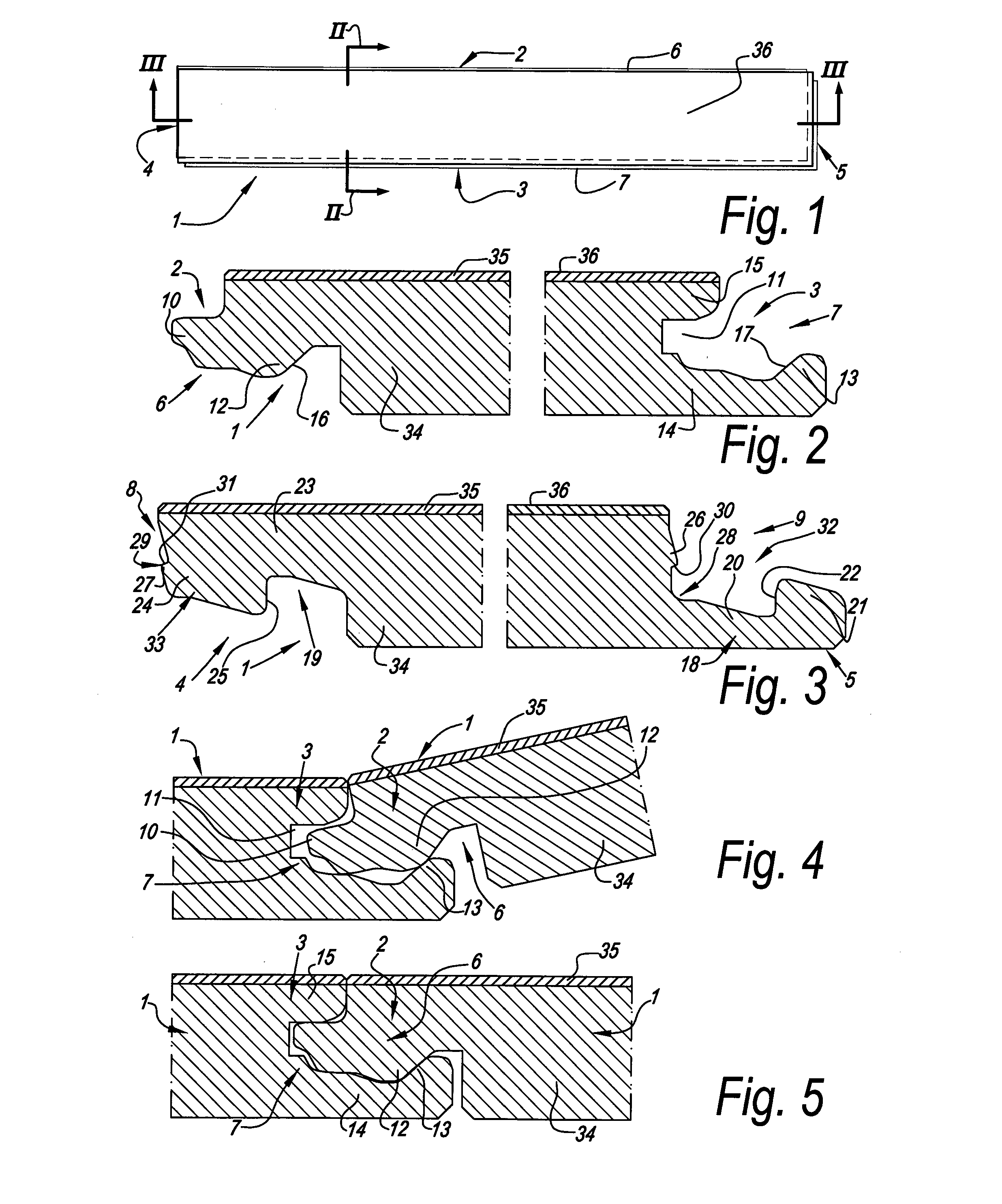
[0113]In FIGS. 1 to 7, an embodiment of a panel 1 according to the invention is represented, which is realized as a floor panel, in which all first five aspects of the invention are applied.

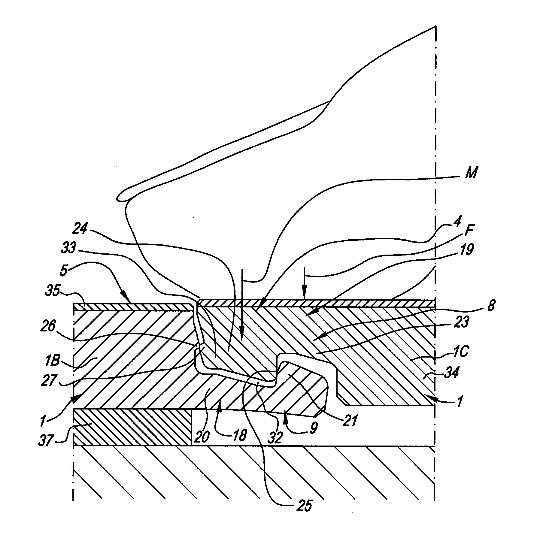
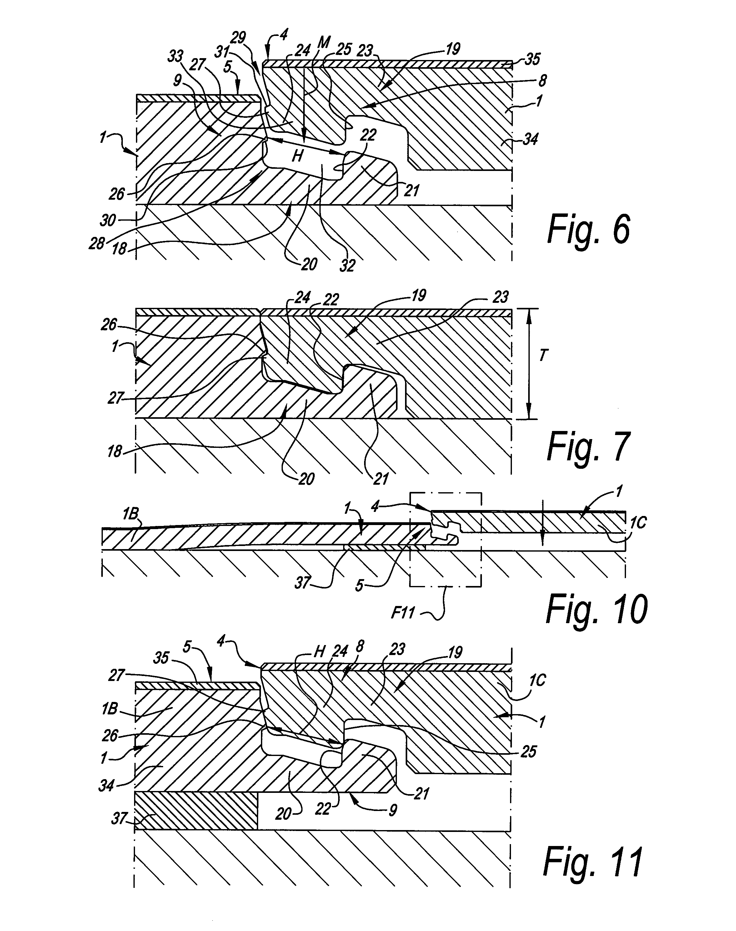
[0114]In the represented example, the panel 1 is made as an oblong rectangular strip and thus comprises a first pair of opposite edges 2-3, which in this case form the long sides of the panel 1, and a second pair of opposite edges 4-5, which form the short sides of the panel 1.

[0115]As is represented more in detail in FIGS. 2 and 3, both pairs of opposite edges 2-3 and 4-5 comprise coupling parts 6-7, 8-9, respectively, which allow to mutually couple a plurality of such panels 1 to each other.

[0116]As specifically represented in the FIGS. 4 and 5, coupling parts 6-7 at the first pair of opposite edges 2-3 are configured such that two of such panels can be coupled to each other at these edges 2-3 in a locking manner by means of a turning movement. Herein, the coupling parts 6-7 form a first lockin...


PUM

PropertyMeasurementUnit
thicknessaaaaaaaaaa
thicknessaaaaaaaaaa
thicknessaaaaaaaaaa

Abstract

A panel for forming a covering, more particularly a floor panel for forming a floor covering, which at least at two opposite edges, comprises coupling parts arranged to couple two of such panels to each other by means of a downward movement of one panel in respect to the other. The coupling parts form a first locking system arranged to lock in the plane of the panels and perpendicularly to the edges, as well as form a second locking system, which effects a locking perpendicularly to the plane of the panels. At least one of the coupling parts is formed at least partially in soft PVC (polyvinyl chloride), as well as at least partially formed from a milled profiled part of this soft PVC.

Description

CROSS REFERENCE TO RELATED APPLICATIONS[0001]This application is a continuation of U.S. application Ser. No. 13 / 518,112, filed Jun. 21, 2012, which is the national stage of PCT / IB2010 / 055693, filed Dec. 9, 2010, which claims priority to European Application No. 09015855.1, filed Dec. 22, 2009, which further claims the benefit of the filing date of U.S. provisional patent application Ser. No. 61 / 333,510, filed May 11, 2010, the entire contents of all of which are incorporated by reference in their entirety.BACKGROUND OF THE INVENTION[0002]1. Field of the Invention[0003]This invention relates to a panel, a covering formed of such panels, and a method for installing such panels.[0004]Primarily, the invention relates to floor panels, more particularly decorative floor panels for forming a floor covering, however, it is not excluded to apply the invention with other forms of coverings, for example, as wall panels, ceiling panels and the like.[0005]The invention relates in particular to p...

Claims


Application Information

Patent Timeline
Patent Type & Authority Applications(United States)
IPC IPC(8): E04F15/02E04F15/10
CPCE04F15/02038E04F15/107E04F15/105E04F2201/0146E04F2201/0153E04F2201/0123E04F2201/0138E04F15/02194B32B3/06B32B2471/00E04F15/02033B32B27/08B32B27/304E04F2201/023
Inventor CAPPELLE, MARK
Owner FLOORING IND LTD
Why Eureka
Try Eureka