Damping force variable shock absorber

a shock absorber and variable technology, applied in shock absorbers, springs/dampers functional characteristics, cycle equipments, etc., can solve the problems of response delay or the like, the damping force is difficult to decrease or increase in any one stroke, and it is difficult to adjust one damping for

Inactive Publication Date: 2016-12-22
SHOWA CORP
View PDF2 Cites 28 Cited by
  • Summary
  • Abstract
  • Description
  • Claims
  • Application Information

AI Technical Summary

Benefits of technology

[0015]According to the damping force variable shock absorber of the present invention, it is possible to provide a compact damping force variable shock absorber capable of realizing different adjustments during the compression-side stroke and the extension-side stroke as initial settings.

Problems solved by technology

In such damping force adjustment-type shock absorber, since the damping force balance between the compression-side stroke and the extension-side stroke is determined by structural factors such as the piston diameter and the piston rod diameter, it is difficult to decrease or increase the damping force in any one of the strokes.
However, when the control valve is electronically controlled, a response delay or the like may occur.
Thus, it is difficult for one damping force adjustment mechanism which uses electronic control to realize different adjustments during the compression-side stroke and the extension-side stroke as initial settings.
Further, although separate damping force adjustment mechanisms may be provided for respective strokes in order to adjust the damping force in the compression-side stroke and the extension-side stroke, the structure may become complex and the manufacturing cost may increase.

Method used


Image

  • Damping force variable shock absorber
  • Damping force variable shock absorber
  • Damping force variable shock absorber

Examples


first embodiment

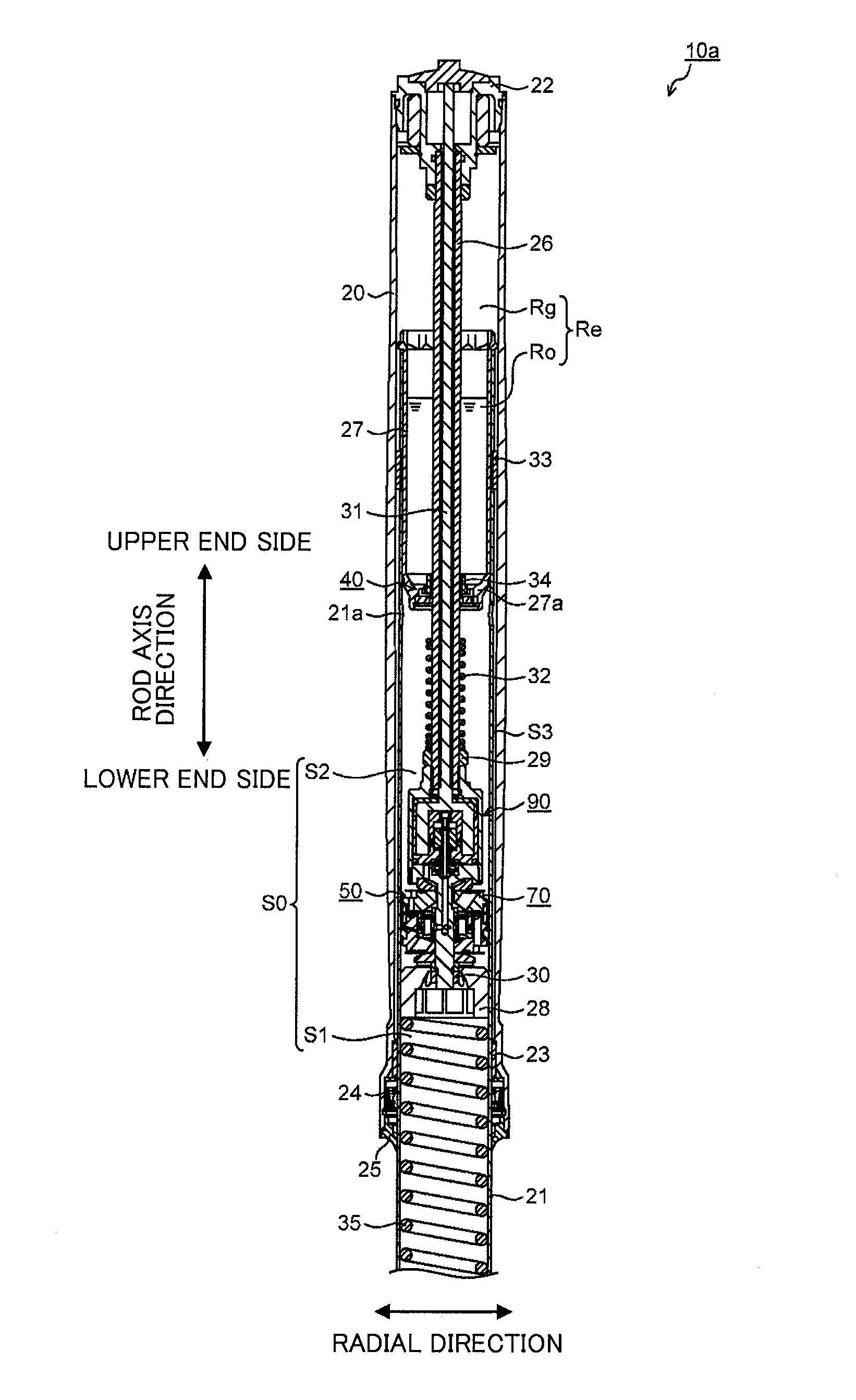
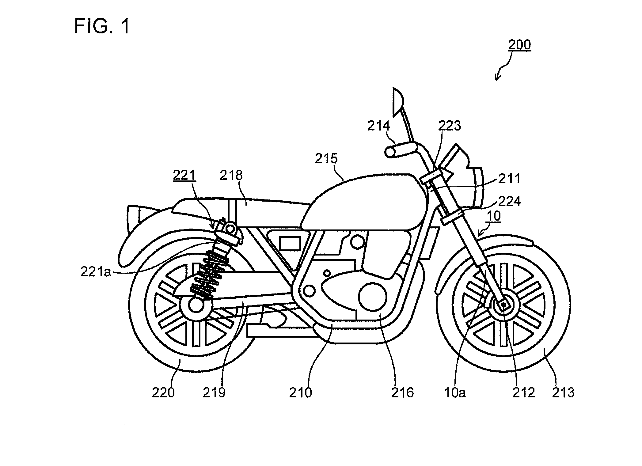
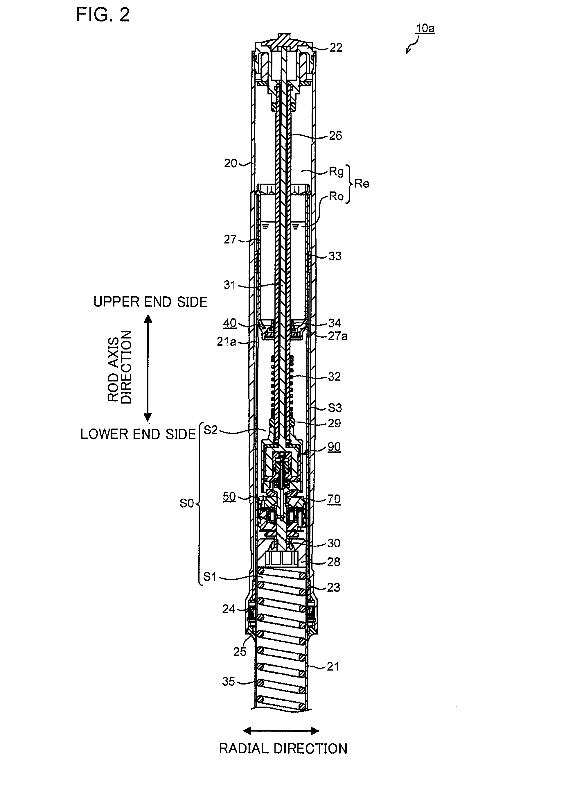
[0031]FIG. 1 is a schematic diagram of a two-wheeled motor vehicle 200 having a damping force variable shock absorber according to a first embodiment. In the present embodiment, a front fork 10 is illustrated as an example of a damping force variable shock absorber. That is, the front fork 10 functions as a damping force variable shock absorber.

[0032]As illustrated in FIG. 1, the two-wheeled motor vehicle 200 includes a vehicle body frame 210 that constitutes a part of a vehicle body, a head pipe 211 attached to a front end of the vehicle body frame 210, a front fork 10 provided on the head pipe 211, and a front wheel 213 attached to a lower end of the front fork 10 with an axle212 interposed.

[0033]The front fork 10 is disposed so as to sandwich the front wheel 213 from left and right sides. Specifically, the front fork 10 includes a first leg 10a and a second leg 10b (not illustrated). Only the first leg 10a disposed on the right side in a traveling direction is illustrated in FIG....

second embodiment

[0139]FIG. 8 is a drawing illustrating a longitudinal cross-section of a damping force variable device 51 of a first leg 10a of a front fork 10 which is a damping force variable shock absorber according to a second embodiment. FIG. 8 illustrates a portion of the inner tube 21 for the sake of convenience. Moreover, the same constituent elements as those of the first embodiment will be denoted by the same reference numerals and redundant description thereof will be omitted or simplified.

[0140]As illustrated in FIG. 8, the communication passage 72d of the damping force variable device 51 allows the pilot chamber 61 and the piston-side oil chamber S1 to communicate with each other. In this case, as illustrated in FIG. 8, one end of the communication passage 72d is open to a side surface of the lower piston member 72 below the sliding sealing member 73.

[0141]One end of the communication passage 72d is open to the gap 76 formed between the inner tube 21 and the piston 70 on the lower end ...


PUM


Abstract

There is provided a compact damping force variable shock absorber capable of implementing different adjustments for a compression-side stroke and an extension-side stroke as initial settings. A damping force variable device in one embodiment includes: a main valve that opens and closes to control flow of oil caused by sliding of a piston in a cylinder, thereby generating damping force; a pilot chamber into which a portion of the flow of the oil is introduced so that internal pressure is applied to the main valve in a valve-closing direction; a pilot valve that opens and closes to adjust the internal pressure of the pilot chamber; and a communication passage that communicates the pilot chamber with a rod-side oil chamber or a piston-side fluid chamber.

Description

CROSS-REFERENCE TO RELATED APPLICATION(S)[0001]This application claims priority from Japanese Patent Application No. 2015-122328 filed on Jun. 17, 2015, the entire contents of which are incorporated herein by reference.BACKGROUND OF THE INVENTION[0002]1. Field of the Invention[0003]Embodiments of the present invention relate to a damping force variable shock absorber.[0004]2. Description of the Related Art[0005]In a two-wheeled motor vehicle, a wheel may be connected to a vehicle body frame via a shock absorber. Examples of the shock absorber include a damping force adjustment-type shock absorber that controls flow of operating fluid (oil) to adjust damping force. For example, JP-2009-281584-A discloses a shock absorber.[0006]In a damping force adjustment-type shock absorber, damping force may be adjusted using the same control valve in a compression-side stroke and an extension-side stroke. A damping force balance between the compression-side stroke and the extension-side stroke is...

Claims


Application Information

Patent Timeline
Patent Type & Authority Applications(United States)
IPC IPC(8): F16F9/46B62K25/08F16F9/18
CPCF16F9/464F16F9/185B62K25/08F16F2228/066B62M7/00F16F13/007F16F9/465F16F9/46
Inventor MIWA, KAZUHIROKUROIWA, NAOYA
Owner SHOWA CORP
Why Eureka
Try Eureka