Light-emitting device

Inactive Publication Date: 2016-12-22
SIGNIFY HLDG BV
View PDF1 Cites 12 Cited by
  • Summary
  • Abstract
  • Description
  • Claims
  • Application Information

AI Technical Summary

Benefits of technology

[0009]The present invention is based on the realization that a light-emitting device providing uniform light may be achieved through a configuration with an optically reflecting layer and a light-transmissive layer separated by an intermediate space with a reflector arranged in the space. The surface of the optically reflecting layer facing the light-transmissive layer is optically reflective and the intermediate space acts as a mixing chamber for light reflected by the optically reflecting layer. The reflector is arranged such that light emitted by the light source is primarily directed towards the optically reflecting layer, which provides for improved uniformity of the light emitted by the light-emitting device, as well as for reduced glare. However, the reflector is further arranged and configured such that a fraction of the light emitted from the light source is directly emitted towards the light-transmissive surface. That means not all the light beams that are redirected by the reflector is redirected towards the optically reflecting layer, but some light beams are reflected by the reflector directly towards the light-transmissive layer. In this way the uniformity of the emitted light from the light transmissive layer is further improved due to a reduced contrast at a border between the reflector and the optically reflecting layer.
[0010]In various embodiments, the reflector comprises a first surface portion and a second surface portion, the second surface portion being closer to the light source than the first surface portion, wherein a fraction of light reflected towards the light-transmissive layer by the first surface portion is larger than a fraction of light reflected towards the light-transmissive layer by the second surface portion. In other words, more light, or a higher fraction of the light, emitted by the light source may be reflected directly towards the light-transmissive layer by the reflector if the emitted light is reflected from a surface portion of the reflector closer to the optically reflecting layer than if reflected from a surface portion further away from the optically reflecting layer. This way, the contrast between the reflector and the optically reflecting layer may be further reduced, which advantageously improves the uniformity further.
[0011]In some embodiments, the reflector comprises an optically specular and an optically diffusive surface portion, wherein a surface fraction of diffusive surface is increasing with increasing distance from the light source in a plane perpendicular to the light-transmissive layer. A specularly reflective surface is a surface where reflected light has a reflecting angle which is equal

Problems solved by technology

When providing lighting devices for example in an acoustic panel it may be diffic

Method used


Image

  • Light-emitting device
  • Light-emitting device
  • Light-emitting device

Examples


Embodiment Construction

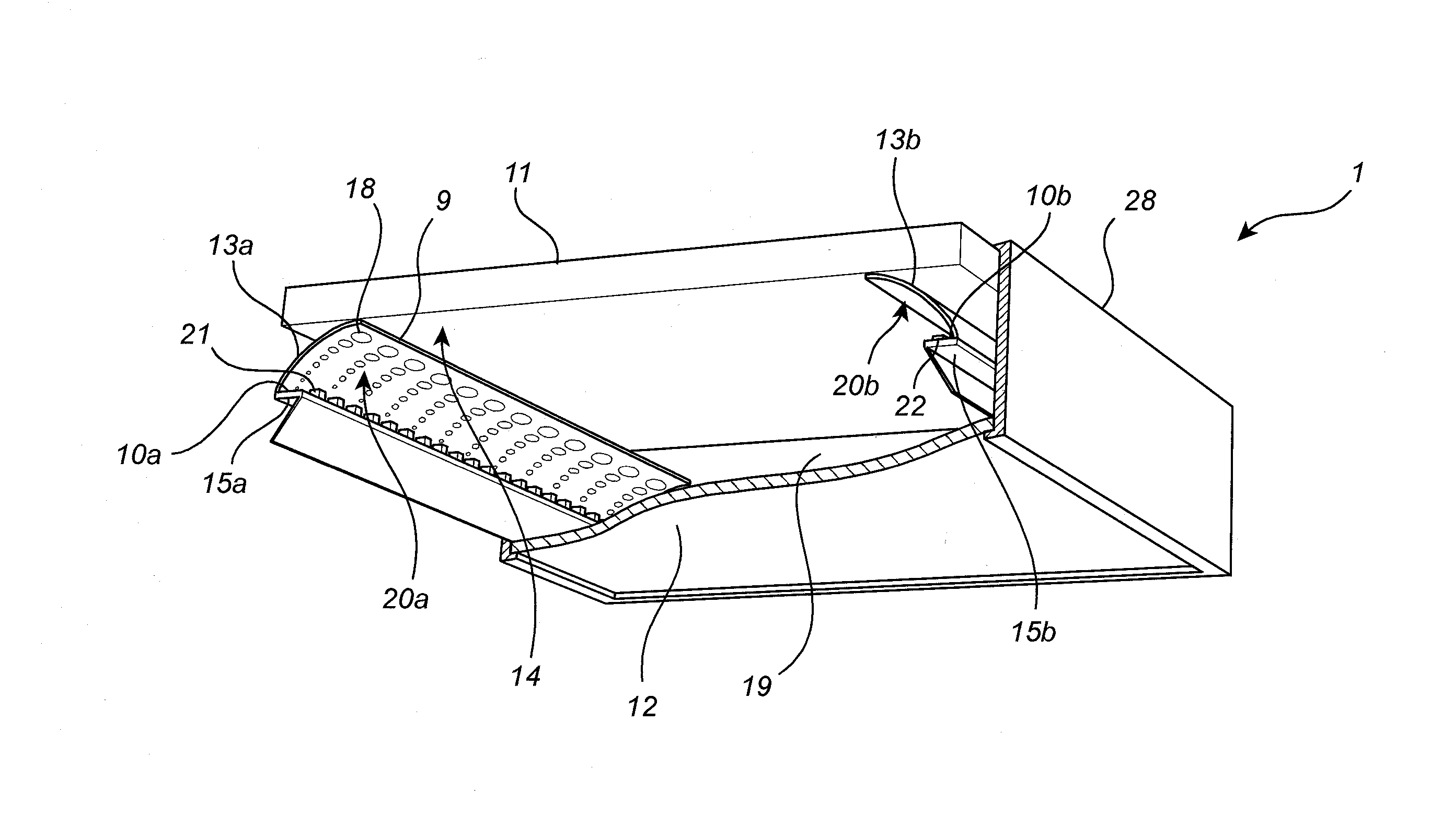
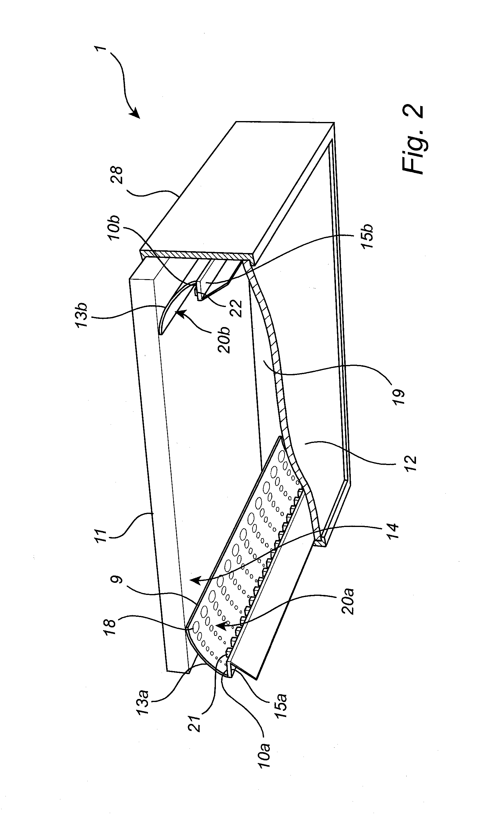
[0028]In the following description, the present invention is mainly described with reference to a light emitting ceiling panel with integrated LED-strips arranged along the edges of the panel and reflectors directing light from the LEDs towards a reflective side of the optically reflecting layer and a fraction of the light reflected directly towards the light-transmissive layer.

[0029]It should, however, be noted that this by no means limits the scope of the invention, which is equally applicable to other applications and other lighting devices, such as light-emitting wall panels, light-emitting ceiling panels, not necessarily with the optically reflecting layer being a sound-absorbing layer. Furthermore, the light source may be any other light source such as another semiconductor light source or a fluorescent light source.

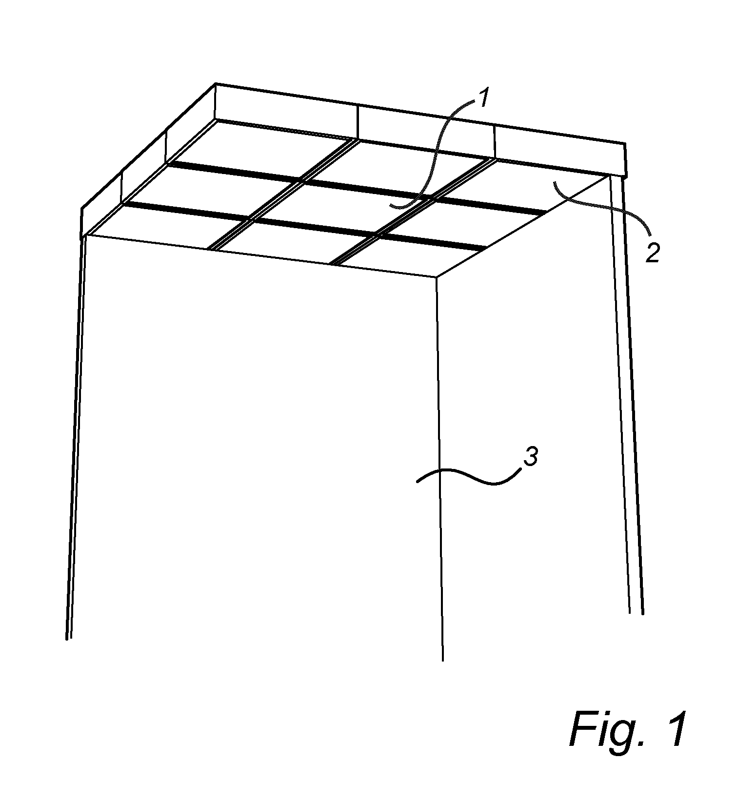
[0030]FIG. 1 schematically illustrates an exemplary application for embodiments of the light-emitting device in the form of a light-emitting panel 1 according to t...


PUM

PropertyMeasurementUnit
Fractionaaaaaaaaaa
Pressureaaaaaaaaaa
Densityaaaaaaaaaa

Abstract

There is provided a light-emitting device (1) that may be mounted in a ceiling. The light-emitting device (1) comprises an optically reflecting layer (11) and a light-transmissive layer (12) arranged such that a space is formed in-between. In the space a light source (10a, 10b) and a reflector (13a, 13b) are arranged such that light emitted by the light source (10a, 10b) is redirected by the reflector (13a, 13b) and emitted primarily towards a reflective side (14) of the optically reflecting layer (11). The reflector (13a, 13b) is arranged to emit a portion of the light directly towards the light-transmissive layer (12). Furthermore, the reflector (13a, 13b) may comprise optically specular portions (20a, 20b, 31) and optically diffusive portions (18, 32, 33, 34, 35) arranged such that a larger surface fraction of the reflector (13a, 13b) comprises diffusive surface portions closer to the optically reflecting layer (11).

Description

FIELD OF THE INVENTION[0001]The present invention relates to a light-emitting device.BACKGROUND OF THE INVENTION[0002]In modern buildings, the building elements used, for example in the ceiling, need to be compatible with various functions in relation to, for example, acoustics and lighting. An example of such a building element may be a ceiling panel with certain desired properties such as acoustic and visual properties.[0003]When providing lighting devices for example in an acoustic panel it may be difficult to achieve uniform lighting while maintaining the desired acoustic properties. It is therefore desirable to provide an improved light-emitting panel that may provide sound-damping and uniform lighting.SUMMARY OF THE INVENTION[0004]In view of the above-mentioned and other drawbacks of the prior art, a general object of the present invention is to provide an improved light-emitting device that provides uniform lighting.[0005]According to a first aspect of the present invention t...

Claims


Application Information

Patent Timeline
IPC IPC(8): F21V7/00F21S8/04F21V7/06F21K9/62E04B9/00F21V7/22
CPCF21V7/0033E04B9/001F21V7/22F21V7/06F21Y2103/10F21K9/62F21S8/04F21V7/0008F21Y2115/10F21V7/005E04B9/32F21V7/28
Inventor THIJSSEN, JOHANNES MARIABOOIJ, SILVIA MARIA
Owner SIGNIFY HLDG BV
Why Eureka
Try Eureka