
Display control apparatus, display controlling method, and program

Active Publication Date: 2016-12-22
CANON KK
View PDF11 Cites 6 Cited by
  • Summary
  • Abstract
  • Description
  • Claims
  • Application Information

AI Technical Summary

Benefits of technology

The technical effect of this patent is to prevent a user from losing their position when they move the focus detection area of an image while the whole angle of view is being displayed.

Problems solved by technology

It is difficult to confirm whether or not focus by autofocus is surely brought on an intended object part while an image of full angle of view is being displayed since a screen of an electronic finder is small and the resolution is limited.
The technique described in Japanese Patent Application Laid-Open No. 2008-211630 has a problem that the positional relationship of the current display area with respect to the whole angle of view is unclear.
That is, it is difficult for a user to understand which part of the whole angle of view is displayed on an electronic finder.
It requires a complicated operation.

Method used


Image

  • Display control apparatus, display controlling method, and program
  • Display control apparatus, display controlling method, and program
  • Display control apparatus, display controlling method, and program

Examples


embodiment 1

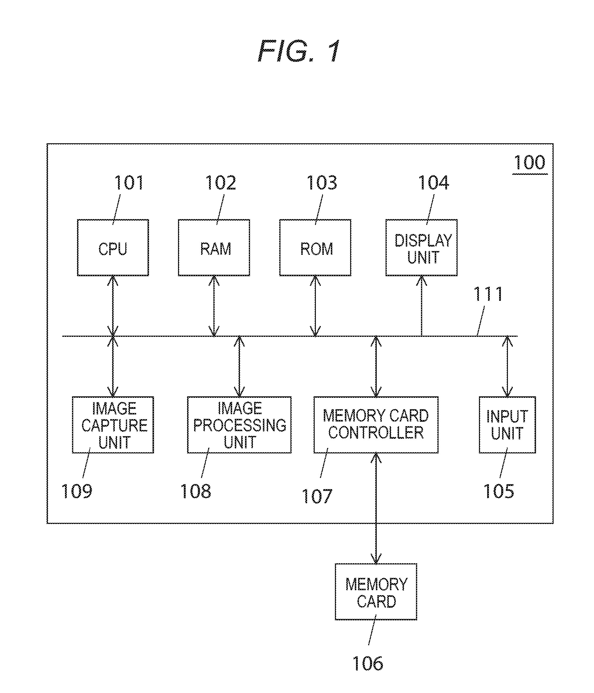
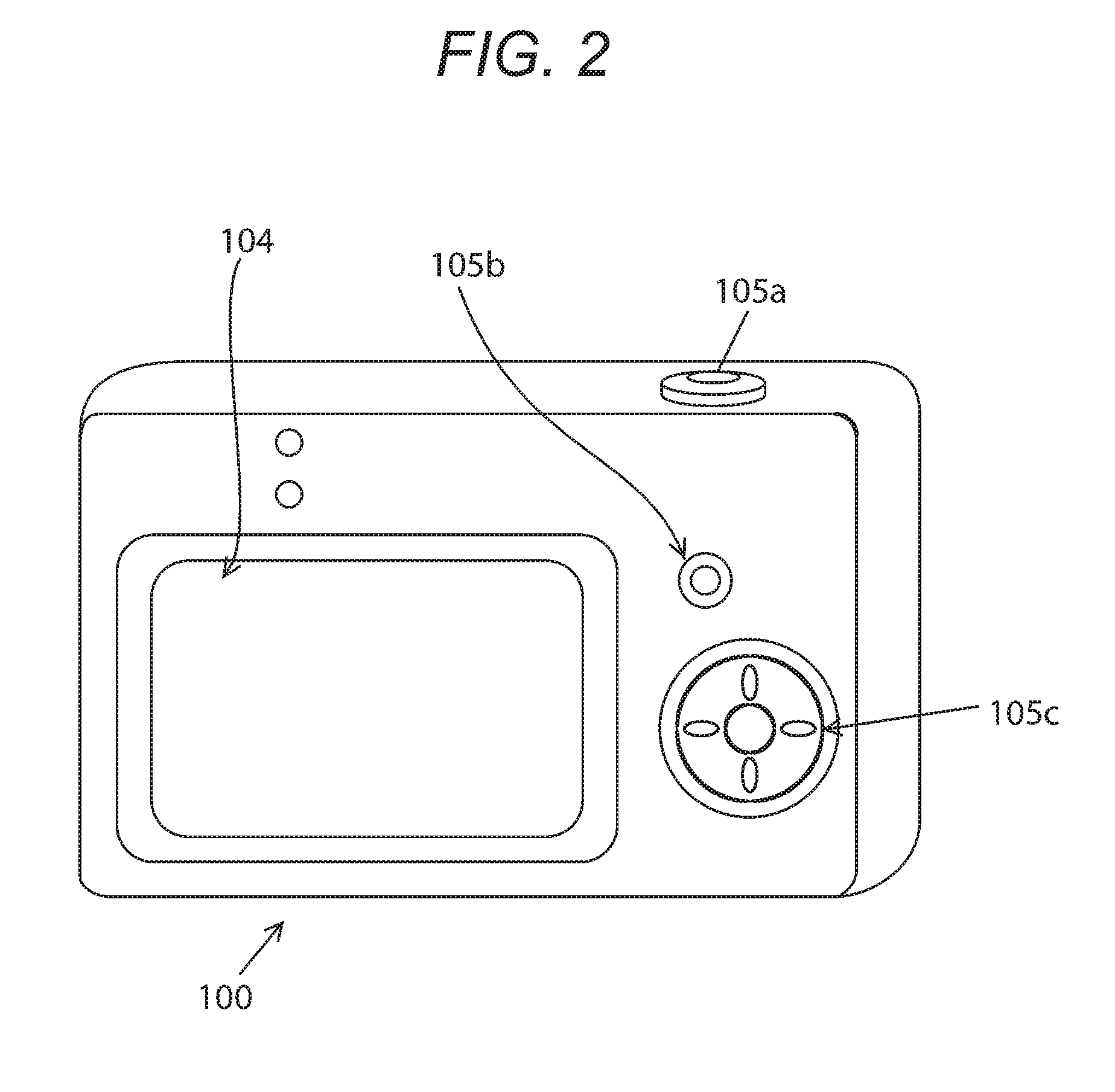
[0020]FIG. 1 is a block diagram showing a schematic structure of a digital camera 100 that is one embodiment of an image capture apparatus according to the present invention. FIG. 2 is a rear perspective view illustrating the digital camera 100 of FIG. 1.

[0021]The digital camera 100 includes a CPU 101, a RAM 102, a ROM 103, a display unit 104, an input unit 105, a memory card controller 107, an image processing unit 108, and an image capture unit 109, and these are connected to an internal bus 111. A memory card 106 is connected to the memory card controller 107.

[0022]The CPU 101 is an arithmetic processing unit for controlling an operation of the digital camera 100 and a control unit for executing various programs according to instructions input by a user via the input unit 105 to perform display control of the display unit 104 and the like. Images and programs for performing various processing described later such as computer booting processing and basic input / output processing ar...

embodiment 2

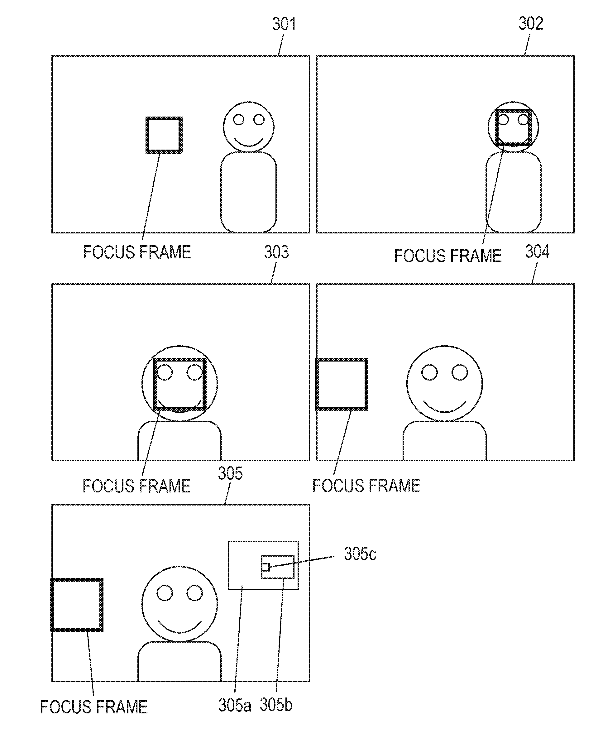
[0046]When the focus frame reaches the display end in the enlargement mode, a part of the captured image that is being enlarged and displayed (enlargement area) together with the focus frame may be moved in the direction of the instruction to move by the user. FIG. 6 is an operation flow chart in the enlargement mode corresponding to such an operation. The operation of each of Steps S601 to S605 is the same as the operation of each of Steps S501 to S505 in FIG. 5. The operations different from those in FIG. 5 will be described in detail.

[0047]When the focus frame does not reach the display end (No in S605), the CPU 101 displays a small screen 305a showing the position of the enlargement area and the focus frame in the whole captured image over the display screen as shown as a display example 305 (S606). The reference numeral 305a shows the whole captured image. The reference numeral 305b shows the area and the position of the part that is currently being enlarged and displayed (enla...

embodiment 3

[0051]As an operation in the enlargement mode, the user may select one of the operation shown in FIG. 5 and the operation in FIG. 6.

[0052]When the focus frame reaches the display end in accordance with the instruction to move by the user, movement of the focus frame is once stopped against continuation of the instruction to move toward the display end. In this situation, the focus frame is moved in the direction in which the focus frame does not cross the display end. When the user again inputs an instruction to move in the direction in which the focus frame crosses the display end, the enlargement mode operates in accordance with the flow shown in FIG. 5 when the operation of the instruction to move is performed between the stop and the predetermined time, and operates in accordance with the flow shown in FIG. 6 when the operation of the instruction to move is performed after the predetermined time has passed.

[0053]By such a control, the user's operation can select movement of the ...


PUM


Abstract

An enlargement area of an image including a focus detection area is enlarged and displayed, and a focus frame is displayed on a display screen over a location corresponding to a position of the focus detection area included in the enlargement area. The focus frame moves on the display screen in accordance with an instruction received via an input unit. When the focus frame moves to a display end, enlargement display is temporarily canceled in order to display the whole image on the display screen, and the focus frame is displayed on the display screen over a location corresponding to a current position of the focus detection area in the whole image.

Description

BACKGROUND OF THE INVENTION[0001]Field of the Invention[0002]The present invention relates to a display control apparatus, a display controlling method, and a program for enlarging and displaying a focus detection area of a captured image.[0003]Description of the Related Art[0004]In a digital camera, an object image and an OSD (On Screen Display) are displayed over each other on an electronic finder with an LCD panel.[0005]In an autofocus camera, contrast and the like of an area (focus detection area) of a part of an image obtained by an image capture element are analyzed, and based on the analysis result, an optical lens is driven to a position where focus is obtained. Although a focus detection area is generally set at the center of a screen in many cases, there are some models in which any location on a screen is designated and an object displayed thereon comes into focus. The focus detection area is displayed by, for example, a green rectangular frame-like shape on the screen of...

Claims


Application Information

Patent Timeline
IPC IPC(8): H04N5/262H04N5/232
CPCH04N5/2628H04N5/23212H04N5/232H04N23/67H04N23/675H04N23/635G06F2203/04806G06T3/40H04N23/62H04N23/69
Inventor SAITO, KYOTA
Owner CANON KK
Features
  • Generate Ideas
  • Intellectual Property
  • Life Sciences
  • Materials
  • Tech Scout
  • Unparalleled Data Quality
  • Higher Quality Content
  • 60% Fewer Hallucinations
Learn More