Image encoding device and method
a technology of image encoding and encoding method, which is applied in the field of image encoding device and a method, can solve the problems of increasing product cost, and achieve the effect of suppressing the decrease in image quality due to encoding
Inactive Publication Date: 2016-12-22
SONY CORP
View PDF7 Cites 10 Cited by
- Summary
- Abstract
- Description
- Claims
- Application Information
AI Technical Summary
Benefits of technology
The patent is about how to make sure that image files are made high quality during encoding. This helps to prevent any decrease in image quality during the process.
Problems solved by technology
Method used
View moreImage
Smart ImageViewing Examples

Examples
first embodiment (
1. First Embodiment (image encoding device)
2. Second Embodiment (image encoding device)
third embodiment (
3. Third Embodiment (image encoding device)
4. Fourth Embodiment (Image Processing System)
[0090]5. Fifth embodiment (multi-view image encoding device / multi-view image decoding device)
sixth embodiment (
6. Sixth embodiment (hierarchical image encoding device / hierarchical image decoding device)
Login to View More PUM
 Abstract
The present disclosure relates to an image encoding device and a method that can suppress a decrease in image quality due to encoding. The image encoding device includes: a control unit configured to restrict a mode of generation of a predicted image, based on prediction of image quality of reference image data to be referred to when generating the predicted image; a prediction unit configured to generate the predicted image according to a mode not restricted by the control unit; and an encoding unit configured to encode image data using the predicted image generated by the prediction unit. The present disclosure can be applied to an image processing device or an image encoding device, for example.
Description
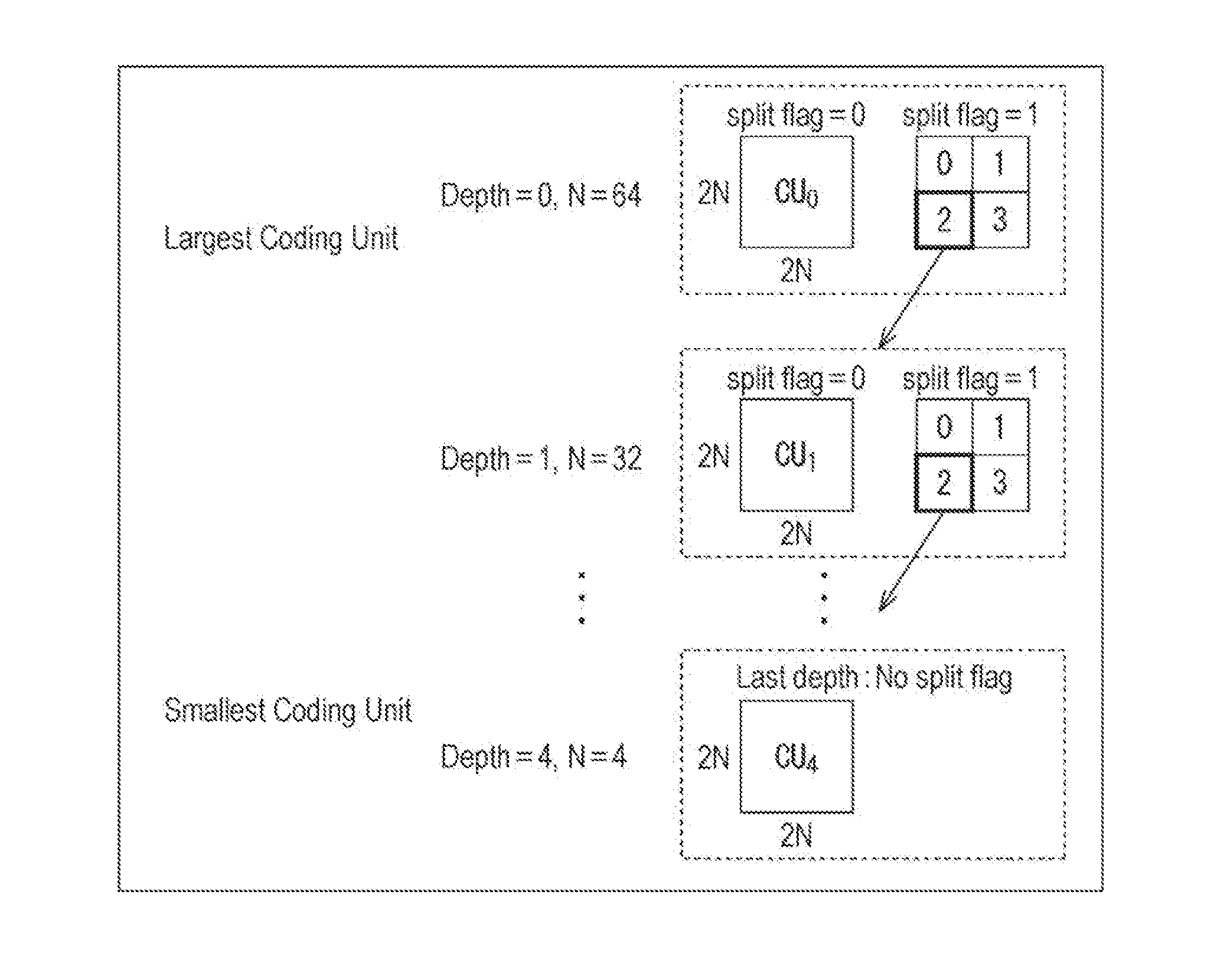
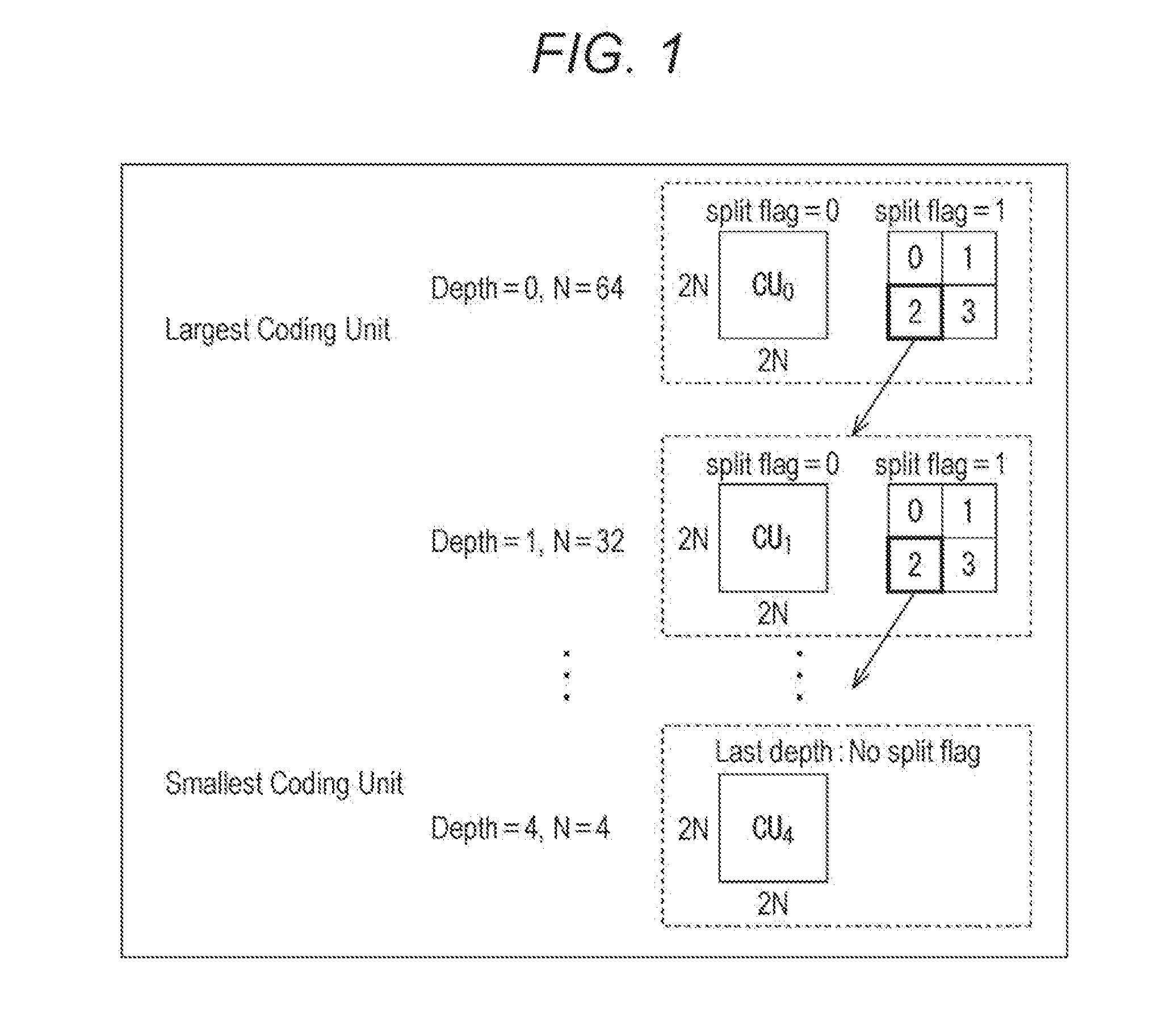
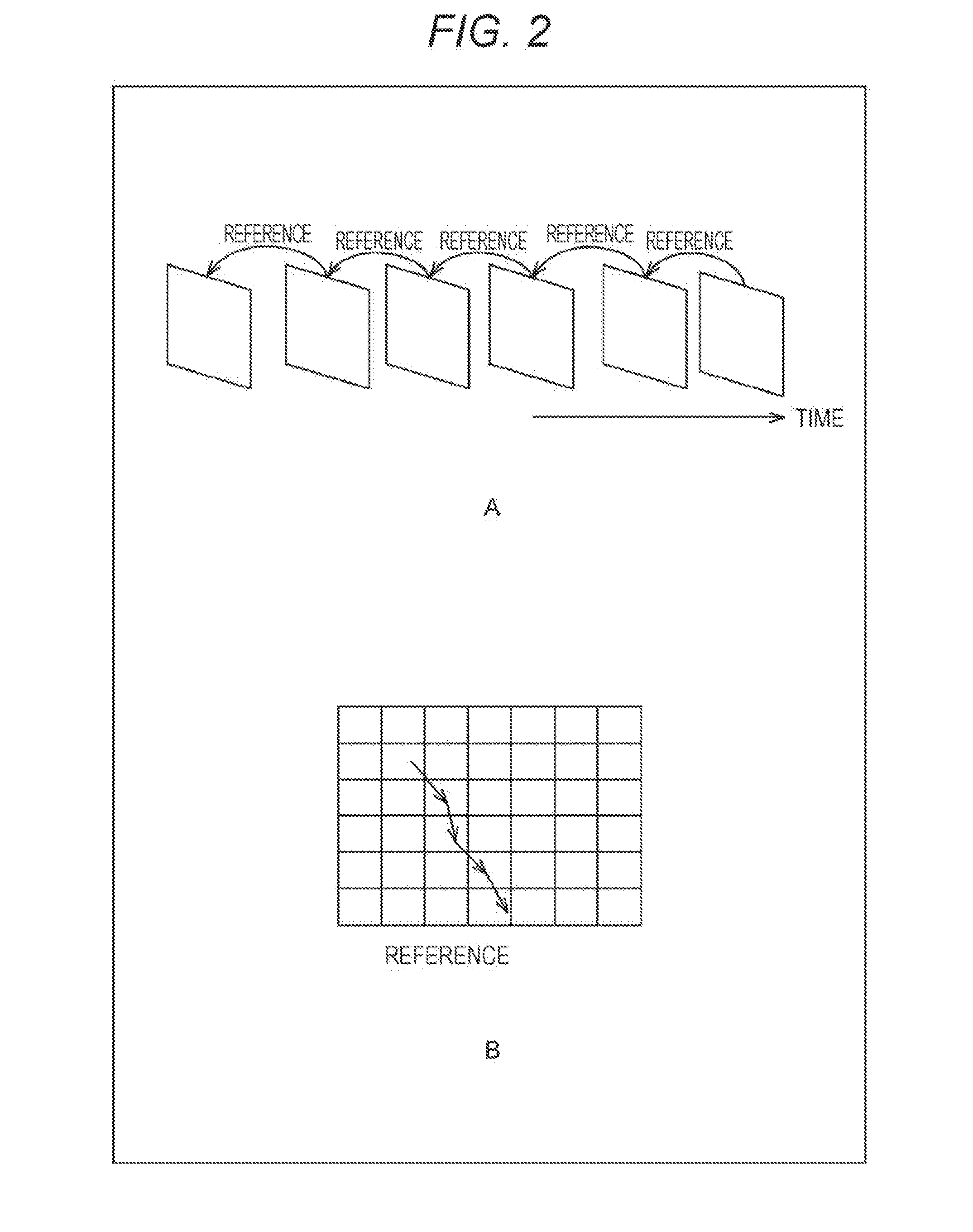
TECHNICAL FIELD[0001]The present disclosure relates to an image encoding device and a method, and especially relates to an image encoding device and a method that can suppress a decrease in image quality due to encoding.BACKGROUND ART[0002]When achieving image encoding by hardware, a frame buffer for storing reference frames is often mounted as an external dynamic random access memory (DRAM) chip separated from a large scale integration (LSI) for encoding. Such a frame buffer needs to store a plurality of reference frames and needs to be accessed at high speed in processing such as motion estimation (ME) and motion compensation (MC), the frame buffer needs to have a sufficiently high data storage capacity and a sufficiently high band to input / output data.[0003]However, due to a recent increase in the capacity of 4K televisions and image data, the data amount handled by image encoders tends to increase. Therefore, a high capacity and a high band are required for the external DRAM chi...
Claims
Login to View More Application Information
Patent Timeline
 IPC IPC(8): H04N19/11H04N19/154H04N19/593H04N19/423H04N19/14H04N19/176
CPCH04N19/11H04N19/14H04N19/154H04N19/593H04N19/423H04N19/176H04N19/503H04N19/109H04N19/33
Inventor NAGUMO, TAKEFUMIUEKI, NOBUOIHARA, TOSHINORILU, SHUOSAKURAI, HIRONARIMORIGAMI, YOSHITAKA
Owner SONY CORP